This thread has been locked.

If you have a related question, please click the "Ask a related question" button in the top right corner. The newly created question will be automatically linked to this question.

LMK04828: confirm that LMK04828 can generate 10MHz clock.

Part Number: LMK04828
Other Parts Discussed in Thread: ADC34J25

Dear product line engineer

   my customer has below question for LMK04828.

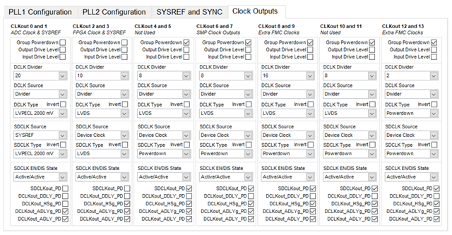
    "Could you help me to double check that this device can generate 10MHz frequency for normal clock? I mean here I don’t want to use the JESD SYSREF/SYNC function."

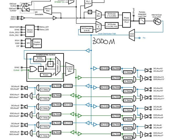
 The desired VCO frequency here is 3000MHz.


thank you very much!

regards,

Bill

  • Hi Bill,

    SDCLK divider is up to 32, SDCLK cannot output 10MHz.

    We have to use SYSREF divider to make 10MHz continuous clock.

  • Hi Noel

    I am Brooke, RF engineer from Philips. I raised up this question for Bill. Thanks for your explaination.

    The VCO1 output here is specified 3000MHz, so I use SDCLK divider to get 300M and 150M clocks for my ADC/DAC usage.

    From your answer, can I confirm that this 10MHz clock can be used for the device clock? I want to use this 10MHz for driving other devices on the PCB board.

    How can I set the SYSREF/SYNC part of the chip to use 10MHz as the device clock? Which items should I take care when I use this 10MHz for device clock in hardware?

    Does this 10MHz frequency get the samilar phase noise/jitter performance like 300M and 150M above?

    Thanks for your reply。

    Best Regards,

    Brooke

  • Hi Brooke,

    The SYSREF block is configurable to generate continuous clock or pulses. As shown in the previous diagram, we are simply using the divider of the SYSREF block to divide down the VCO clock. The output from SDCLKout1 is a continuous 10Mhz clock. 

    SYSREF divider has the same performance as the Clock divider, their additive jitter is pretty much the same.

    It is recommended to use TICS Pro to setup the desired configuration in order to get the correct register setting. Setup the correct register setting by reading the datasheet is difficult.

  • Hi Noel

    Thanks for your quickly rely. 

    On my hand, there is one ADC34J25 demo board with LMK04828. Here I want to use external reference clock(coming from keysight N9010A 10MHz out) for locking both PLL1 and PLL2. Here I want to use dual-loop mode for the LMK04828. This demo board has one 100MHz VCXO for the PLL1.

    Please see my configuration for the PLL1, PLL2, SYSREF/SYNC and CLK output below:

    From the demo board, I can see the LED D4 is green while LED D1, D2 and D3 are not open.

    From my viewpoint, I think the LMK04828 is not locked now.

    Could you please help me to check the configuration above about the LMK04828? Thanks for your time.

    Please see the VCXO part as below for PLL1

  • Hi Brooke,

    Can it possible to share the configuration file used for LMK04828 programming to have a look on register write details?

    From the config images, STATUS_LD1 (D3) should ON for PLL1 lock and it seems it is not locking the PLL1.

    Below is the quick updated config file FYR. you can convert in ADC GUI expected config format and change the appropriate output channel then try in your board.

    LMK04828_10MCLKin1_100MOSCin_10MSYSREF.tcs

    R0 (INIT)	0x000090
    R0	0x000010
    R2	0x000200
    R3	0x000306
    R4	0x0004D0
    R5	0x00055B
    R6	0x000600
    R12	0x000C51
    R13	0x000D04
    R256	0x010014
    R257	0x010155
    R258	0x010255
    R259	0x010301
    R260	0x010422
    R261	0x010500
    R262	0x0106F0
    R263	0x010755
    R264	0x01080A
    R265	0x010955
    R266	0x010A55
    R267	0x010B00
    R268	0x010C02
    R269	0x010D00
    R270	0x010EF1
    R271	0x010F11
    R272	0x011008
    R273	0x011155
    R274	0x011255
    R275	0x011300
    R276	0x011402
    R277	0x011500
    R278	0x0116F9
    R279	0x011700
    R280	0x011818
    R281	0x011955
    R282	0x011A55
    R283	0x011B00
    R284	0x011C02
    R285	0x011D00
    R286	0x011EF9
    R287	0x011F33
    R288	0x012008
    R289	0x012155
    R290	0x012255
    R291	0x012300
    R292	0x012402
    R293	0x012500
    R294	0x0126F9
    R295	0x012700
    R296	0x012808
    R297	0x012955
    R298	0x012A55
    R299	0x012B00
    R300	0x012C02
    R301	0x012D00
    R302	0x012EF9
    R303	0x012F00
    R304	0x013006
    R305	0x013155
    R306	0x013255
    R307	0x013300
    R308	0x013402
    R309	0x013500
    R310	0x0136F9
    R311	0x013733
    R312	0x013825
    R313	0x013903
    R314	0x013A01
    R315	0x013B2C
    R316	0x013C00
    R317	0x013D08
    R318	0x013E03
    R319	0x013F00
    R320	0x01400B
    R321	0x014100
    R322	0x014200
    R323	0x014313
    R324	0x0144FF
    R325	0x01457F
    R326	0x014610
    R327	0x01471A
    R328	0x014802
    R329	0x014942
    R330	0x014A02
    R331	0x014B16
    R332	0x014C00
    R333	0x014D00
    R334	0x014EC0
    R335	0x014F7F
    R336	0x015003
    R337	0x015102
    R338	0x015200
    R339	0x015300
    R340	0x015478
    R341	0x015500
    R342	0x015601
    R343	0x015700
    R344	0x015896
    R345	0x015900
    R346	0x015A0A
    R347	0x015BD4
    R348	0x015C20
    R349	0x015D00
    R350	0x015E00
    R351	0x015F0B
    R352	0x016000
    R353	0x016101
    R354	0x0162A4
    R355	0x016300
    R356	0x016400
    R357	0x016506
    R369	0x0171AA
    R370	0x017202
    R380	0x017C15
    R381	0x017D33
    R358	0x016600
    R359	0x016700
    R360	0x016806
    R361	0x016959
    R362	0x016A20
    R363	0x016B00
    R364	0x016C00
    R365	0x016D00
    R366	0x016E13
    R371	0x017300
    R386	0x018200
    R387	0x018300
    R388	0x018400
    R389	0x018500
    R392	0x018800
    R393	0x018900
    R394	0x018A00
    R395	0x018B00
    R8189	0x1FFD00
    R8190	0x1FFE00
    R8191	0x1FFF53
    

    Thanks!

    Regards,
    Ajeet Pal

  • Hi Pal

    Thanks for your reply.

    I think I find the root cause.

    In my configuration, I only changed the register 0x15B from 0x14 to 0xD4, and hen the STATUS_LD1 (D3) is on with green color.

    Could you please let me confirm this is the status for the LMK being locked now?

    Please see this register 0x15B. What's the reason from the value from 0x14 to 0xD4, the LMK can locked? It's better you can give me more explaination.

    With many thanks.

  • Hi Brooke,

    PLL1_WND_SIZE is set for the digital lock detect for PLL1. The window size set based on phase error between reference and feedback of PLL1. If there is more phase error between them, window size need to be increase. and STATUS_LD1 will show the lock detect for PLL1. PLL1_WND_SIZE POR default is 0x3 and keep the same, lower window size can go for higher PFD frequency.

    Yes, if STATUS_LD1 (D3) is ON, it indicates the PLL1 locked for the given settings.

    Thanks!

    Regards,

    Ajeet Pal

  • Hi Pal

    Thanks for the detailed explanation.

    Here I got one EVM- TSW14J56, which I used for connecting the other EVM-ADC34J25. When I connected these two EVMs with FMC connectors, I open the GUI for capture the data, but here I got one isse as below on the HSDC Pro.

    Could you please let me know what's the issue behind? Should I need to use other connectors between these two EVMs?

    With many thanks.

  • Hi Brooke,

    I'll re-assign this thread to data converter team, who can support you on HSDC Pro tool issue/error.

    Thanks!

    Regards,

    Ajeet Pal

  • Thanks Pal. I have fix the issue. Because of my current limitation on the power supply.

    Thanks again.

  • Thanks! Then I'll close this thread assuming issues are resolved.

    Feel free to reply to this thread or open new for any further queries.

    Thanks!

    Regards,

    Ajeet Pal