Other Parts Discussed in Thread: SE555, SE555M,
Dear Whom It May Concern,
-INQUIRY-
We were informed from our customer that the following device has failed RGA testing during DPA and received the questions.
P/N : 5962-9855501VPA
Date Code : 1935A
-RGA Result-
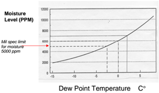
0.87vol% against RGA requirement 0.5vol% (MIL-STD-883, TM1018)
-Questions form customer-
- Will this device sealed under atmospheric pressure or under reduced pressure?
(RGA is tested as if the device is sealed under atmospheric pressure)
- Are there any reports of anomaly or malfunction for this date code (1935A)
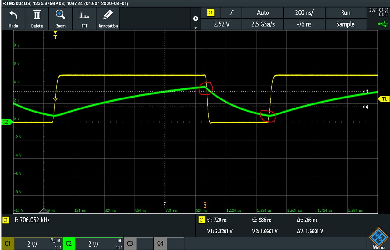
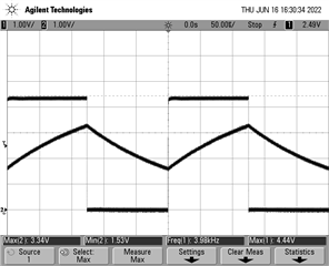
- Experiencing different frequencies from design value.
We built 2 models and the result was 3400Hz for both of them against Design value = 4089Hz output.
The frequency relies on the external condensers but we believe the cause is not due from external condensers since error in component constants are ±1%.
Therefore, we came to the conclusion this anomaly occurred due to the device itself.
We have built experimental models in previous stage and worked as expected.
Would you please kindly provide your knowledge for this phenomenon?
Hope you could kindly provide your knowledge to solve the questions.
Thank you for your kind support.
Kind Regards,
Yohei Kusachi