This thread has been locked.

If you have a related question, please click the "Ask a related question" button in the top right corner. The newly created question will be automatically linked to this question.

LMX2615EVM-CVAL: LMX2615EVM-CVAL Output Power

Part Number: LMX2615EVM-CVAL
Other Parts Discussed in Thread: LMX2594

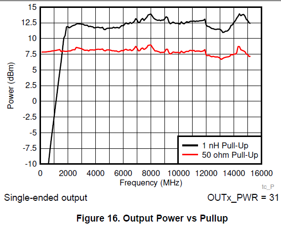
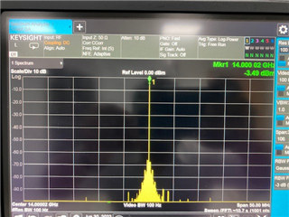
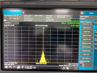
The output power has been observed and measured to be inconsistent across the output spectrum for our eval board.  We've been unable to replicate any sort of flat frequency response similar to that seen in the datasheet, regardless of being at any set OUTx_PWR level across the output spectrum, regardless of output power.

As a follow side question, how should the difference between specified output powers be reconciled from the datasheet?

  • Hi Nolan,

    We de-embedded the board losses for our measurements, which greatly smoothed the observed results. The losses are not great for our PCB, with a huge dip at around 13GHz:

    I'm thinking the "typical" datasheet results are not great, and may be a hedge against measurement variation (path length, connector fit, etc). The graph for single-ended output power is going to be the most accurate source for actual output power, with the caveat that board losses were de-embedded on an equivalent coupon board.

    Regards,

    Derek Payne

  • Hi Derek,

    Thanks for getting back to me on this. Would you be able to share a .csv of the your measured board losses so that we may back them out of our own output power measurements?  I don't believe that this is all of the output losses that we are seeing.

    Do you have any additional suggestions to possibly troubleshoot our test setup to make sure we're running it in an optimal way?

  • Nolan,

    I've attached it as a .tsv (tab-separated - we have some European customers for whom csv frequently becomes a mess).

    measured board loss across frequency.tsv

    The biggest issue is the challenges with load matching at high frequency, especially given the longer leads on the LMX2615 relative to the commercial QFN of the LMX2594, and the impedance discontinuities this creates. Even if we can measure a coupon board, we might not be accurately measuring the impedance discontinuity as the signal travels from the output buffer to the PCB (through bondwires, leadframe, etc).

    To some extent this extra error can be corrected using a microwave tuner module. You would set the tuner up to present matched impedance on the input and 50Ω impedance on the output,  but at some point the losses incurred by the length of the tuner path are large enough that they can affect the results - ideally if the tuner can de-embed its own power losses it saves you a great deal of time and minimizes potential sources of error, but manual de-embedding is possible with a network analyzer and some patience.

    There aren't really many debugging "tricks" that can improve power by a substantial amount. The typical advice to use a 6dB pad or something similar to mitigate layout-related reflections would greatly reduce the usable output power, and in practice we've found it doesn't help that much anyway. Signal amplitude was much higher using inductive coupling, but the overall amplitude was somewhat inconsistent and we started to lose the signal below about 2GHz - this helps a lot with matching to correct out the error, and mostly powers through the remaining board losses. It becomes feasible with inductive pull-up to add a 6dB pad between inductor and output, which might help stabilize the output power.

    Hopefully that helps some...

    Regards,

    Derek Payne

  • This is a lot of great feedback, thanks again for the help. Have been working with the eval board up to this point but if we get to the point of layout I'll be revisiting to see what can be incorporated into our design.

  • Backing out the board losses improved our output power consistency a little bit, but I'm not sure if there's a something else afflicting our output power. We have our roll-off around 14 GHz & it doesn't seem to recover as much as your board loss plot does afterwards.

    Copied are my plots for output power measured directly from the LMX eval board output & then again but with your provided board losses de-embedded.

    I know we're not measuring at the highest of resolutions, but do these results suggest that something else is going on?

  • Hi Nolan,

    Here, it seems the measured output is reducing after 13 GHz and would be suspecting on the setup issue.

    Could you look back on the setup and used RF cables, which may have more losses at very higher frequencies and need to compensate those losses also.

    Thanks!

    Regards,
    Ajeet Pal

  • Hi Ajeet,

    Apologies for the late response. There should be no additional insertion loss to account for in the setup, the power sensor was attached directly to the output of the LMX evaluation board.

    -Nolan

  • Hi Nolan,

    I would be surprising to have very less output power at higher output frequencies (beyond 13GHz) in your measurement.

    Below are the measured data on LMX2615EVM at 13G,14G and 15GHz and these are good enough (RF cable loss included - 1dB) - Direct LMX output.

    P.S. - Please neglect the close-in spurs, OSCin reference is not good for this measurement.

    Thanks!

    Regards,

    Ajeet Pal