This thread has been locked.

If you have a related question, please click the "Ask a related question" button in the top right corner. The newly created question will be automatically linked to this question.

LMK04610: Jitter Cleaning

Part Number: LMK04610

Hello,

Apologies if I am missing this in the datasheet, but I am confused on how to best select a VCXO for the LMK04610 device for putting the device into jitter cleaner mode. My current application has a clock input that can vary depending on the use case of the system. If I do select a VCXO for cleaning does that limit the flexibility I can have with the input clock to the system?

Let me know if further clarification is needed.

Thanks,

Ryan

  • Hi Ryan,

    LMK04610 supports the integer PLL, which does requires the integer division input clock, VCXO with integrated VCO frequencies, considering PLL1_R and PLL2_R dividers. Hence, VCXO frequency should be selected based on required PLL2 VCO frequency and ultimately required output frequency. Using as jitter cleaner, PLL1 input frequency can be vary but it would required higher division ratio and PLL1 phase detector frequency should go low.

    If you have any frequency plan, can use the TICS pro tool and optimized it for various input frequencies and required output frequencies.

    Thanks!

    Regards,

    Ajeet Pal

  • Hi Ajeet,

    Thank you for this response. If the VCXO should be selected based on the PLL2 frequency, do you know any resources that describe how to select a PLL2 VCO frequency? I am newer to the clocking side of things and could use assistance on how to design around this.

    Thanks,

    Ryan

  • Hi Ryan,

    PLL2 supports VCO frequency range from 5870 to 6175MHz and your output frequencies would be integer division VCO frequency.

    To have better phase noise performance of the LMK04610 (PLL2), PLL2 should have higher phase detector frequency (PFD). Hence, your VCXO frequency should be as much as high possible (if, any phase noise critical requirement) and if could find integer division VCXO, can use the PLL2_R divider and optimized the PLL.

    Ex: Fout - 1GHz requirement, you could choose VCO frequency of 6GHz and to have higher PLL2 phase detector frequency (say 200M), you can have VCXO frequency 100MHz (use PLL2 input doubler mode) or can have other optimized VCXO frequency using the PLL2 input divider (PLL2_R).

    Thanks!

    Regards,

    Ajeet Pal

  • Hi Ajeet,

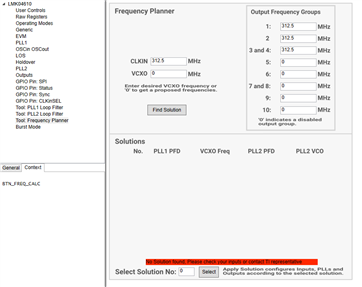
    Apologies on the delay as I had to tackle a few other matters. I think what you are saying is making sense, but I am struggling to use the TI tool (TICS Pro) to assist with connecting the dots between your comment and our design. I was playing with the parameters of the PLLs, but I am still getting lost. At this point, I was going to use the frequency planner, but it is not mentioning there are any solutions to my inputs. Would you be able to help inform what I am doing incorrectly? My current plan is to have two LMK04610 devices. One cascading the other. The first is what I am trying to set up now and will act as a buffer for the input frequency and will have the jitter cleaning functionality if possible. I was selecting 0 for the VCXO frequency to see what it would provide.

    Thanks again,

    Ryan

  • Hi Ryan,

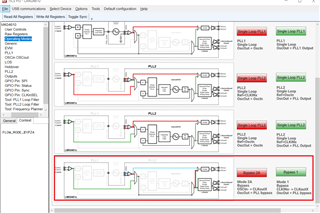
    If you want to have your first LMK04610 in bypass/buffer mode, you can't be having jitter cleaner functionality. 

    For buffer mode, you can follow the Bypass 1 Mode, which can provide the CLKinX input to CLKout output.

    For having jitter cleaner option, you need to operate in dual PLL mode and VCXO frequency should be based on selected internal VCO frequency.

    Thanks!

    Regards,

    Ajeet Pal