Other Parts Discussed in Thread: USB2ANY, LMK04832
TICS Pro uses the USB2ANY device (HPA665) to write to the registers of LMK04823EVM. I would like to create a Python script that does the same. I have the TICS Pro saved file and the Hex Register Values text file (as attached below) and I would like to program the registers with the values in the text file.
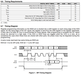
What should the baud rate be set to for SPI communication?
How should data sent via SPI protocol to the slave device? E.g. writing bytes, etc?
It would be much more convenient for me to run a script to program the device with Raspberry Pi than having to start windows and TICS Pro to program it every time I power up the device. Any constructive advice is very much appreciated, as I have been trying to figure it out for months with little to no success. Thanks in advance!
R0 (INIT)	0x000090
R0	0x000010
R2	0x000200
R3	0x000306
R4	0x0004D1
R5	0x000563
R6	0x000650
R12	0x000C51
R13	0x000D04
R256	0x01002C
R257	0x01010A
R258	0x010201
R259	0x010340
R260	0x010400
R261	0x010500
R262	0x010601
R263	0x010755
R264	0x01082C
R265	0x01090A
R266	0x010A01
R267	0x010B40
R268	0x010C00
R269	0x010D00
R270	0x010E01
R271	0x010F55
R272	0x01102C
R273	0x01110A
R274	0x011201
R275	0x011340
R276	0x011400
R277	0x011500
R278	0x011601
R279	0x011755
R280	0x01182C
R281	0x01190A
R282	0x011A01
R283	0x011B40
R284	0x011C00
R285	0x011D00
R286	0x011E01
R287	0x011F55
R288	0x01202C
R289	0x01210A
R290	0x012201
R291	0x012340
R292	0x012400
R293	0x012500
R294	0x012601
R295	0x012755
R296	0x01282C
R297	0x01290A
R298	0x012A01
R299	0x012B40
R300	0x012C00
R301	0x012D00
R302	0x012E01
R303	0x012F55
R304	0x01302C
R305	0x01310A
R306	0x013201
R307	0x013340
R308	0x013400
R309	0x013500
R310	0x013601
R311	0x013755
R312	0x013825
R313	0x013900
R314	0x013A00
R315	0x013B18
R316	0x013C00
R317	0x013D08
R318	0x013E03
R319	0x013F0B
R320	0x01400F
R321	0x014100
R322	0x014200
R323	0x014311
R324	0x014400
R325	0x014500
R326	0x014608
R327	0x01471B
R328	0x014802
R329	0x014942
R330	0x014A03
R331	0x014B06
R332	0x014C00
R333	0x014D00
R334	0x014EC0
R335	0x014F7F
R336	0x015001
R337	0x015102
R338	0x015200
R339	0x015300
R340	0x015478
R341	0x015506
R342	0x015600
R343	0x015700
R344	0x015896
R345	0x015900
R346	0x015A7D
R347	0x015BD4
R348	0x015C20
R349	0x015D00
R350	0x015E1E
R351	0x015F0B
R352	0x016000
R353	0x016180
R354	0x0162AC
R355	0x016300
R356	0x016400
R357	0x01650C
R361	0x016958
R362	0x016A20
R363	0x016B00
R364	0x016C00
R365	0x016D00
R366	0x016E13
R371	0x017310
R375	0x017700
R386	0x018200
R387	0x018300
R358	0x016600
R359	0x016702
R360	0x016871
R1365	0x055500


