This thread has been locked.

If you have a related question, please click the "Ask a related question" button in the top right corner. The newly created question will be automatically linked to this question.

TPL5111: Application Help

Part Number: TPL5111

Hello Team,

I'm posting on behalf of my customer, please see the inquiry below:

I am designing a prototype with the TPL5111 chip but I am getting very unpredictable time between to wake up timing.

I put a resistor of 169k Ohm between the DELAY/ M_DRV  pin and Ground pins to have the chip waking up a micro controller every around 2h but it keep waking up every 5 minutes to 2hours in a way I don't manage to control.

 I put enclosed a picture of the layout I have, maybe that could help.

Prototype.zip

 Could you let me know if I am doing something incorrectly?

Thanks in advance,

Regards,

Renan

  • Hi Renan,

    As you know, the application schematic is very simple and straight forward, there is nothing wrong I can tell from your schematic and layout.

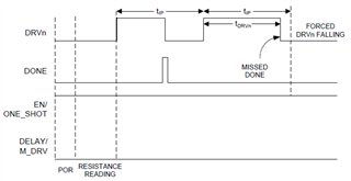
    From the layout, in addition to the resistor, I noticed that the DELAY pin is also connected to somewhere else. Make sure TPL5111 sees only the resistor during the resistance reading period, otherwise, the wake up timing may be inconsistent. 

  • Hello Noel,

    Thank you for your input.
    To answer you about the "DELAY pin is also connected to somewhere else.".
    This trace after the resistance is connected to a momentary push button, when the micro controller needs to waken up manually.
    When the TPL5111 is powered on, this trace is not connected to anything as the push button is not pressed.
    I was wondering is the problem would be coming from parasitic capacitance. Maybe I have too thick traces from the TPL5111 which are too close to each other? Would this be a reason?

    Regards,

    Renan

  • Hi Renan,

    This is not a high frequency device, parasitic is not a matter. 

  • Hello Noel,

    Ok understood.
    Do you have any idea what could be causing this issue then?
    If this helps, this is made on a 2 layers board.

    Regards,

    Renan

  • Hi Renan,

    No, I don't have any guess, the schematic is too simple that it is hard to tell what might be the root cause.

    One thing you can try, just an experiment, is to add a 10k ohms shunt resistor at the DONE pin.