This thread has been locked.

If you have a related question, please click the "Ask a related question" button in the top right corner. The newly created question will be automatically linked to this question.

TLC555: Triggered ramp generator

Part Number: TLC555
Other Parts Discussed in Thread: NE555, , OPA172, OPA197

Hi All,

we are designing a triggered ramp generator, when we have trigger impulse we should generate a ramp from 400mV to 8V  with adjustable ramp time.

i will need a potentiometer to adjust the time of the ramp from 1ms to 100ms ( user selectable via potentiometer). eg i set to 10ms, meaning the ramp must go from 400mV to 8V in 10ms.

1) I would like to use NE555 or TLC555 , which one do you suggest to use ?


2) The 555 should operate in monostable operation like on Figure 9 in DS but i want to replace the Ra resistor with a adjustable current source to get a linear ramp on the capacitor.

do you maybe have a simple implementation on how to do this with 555 timer?

and then i will need to buffer the voltage from capacitor to adjust the levels tp 400mV and 8V and to use this signal to drive an actuator.

Br,

D.

  • Hello,

    I am currently looking into this and will respond by the end of business day tomorrow. 

    Best Regards, 

    Chris Featherstone

  • Hello,

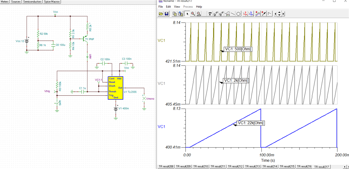
    Here is an idea for your design criteria. I swept R5 with different values from 500 ohm to 22kohm. R1 and R5 control the current that charges the capacitor C1. The gnd pin of the TLC555 can be biased up to 400mV as shown below. I have attached the simulation below. I recommend the TLC555. Let me know what you think. 

    TLC555 Ramp Generator.TSC

    Best Regards,

    Chris Featherstone

  • Hi Chris,

    thank you for the replay, this looks great.

    I also  researched and came across same circuit, but i have additional questions.

    Because i need adjustable ramp time, i can use a potentiometer instead of R5 to adjust the time.

    1)

    My question is how is the bias voltage for the PNP selected ( R1 and R4 resistor) ? Why 9.6V?

    The PNP should always work in Active region (Ve>Vb>Vc) and Vc will change from 0.4V to 8V ( 2/3*12V)

    So Vb should be 0.7V grater than max Vc is that the reason for Vb = 9.6V ?

    2)

    the 0.4V instead of TLC555 GND is nice, please can you explain where in datasheet of TLC555 is stated that this is allowed?

    Also do you know a TI reference that can supply 400mV ( eg. like analog devices LT6650) ? Or any other Ti solution for 400mV ? ( eg LDO ...)

    3) what is the purpose of R23,R6 and C6?

    Best Regards,

    D.

  • Hello D.,

    Yes this is a clever circuit. I attempted a few different avenues and this seems to be the best option. The decision for R1 and R4 only matters to keep the device active like you mentioned. This can be adjusted but was a first pass in order to get a functioning circuit. The bias voltage will determine the charging current set by R5. R5 and R1 can be adjusted as desired. 

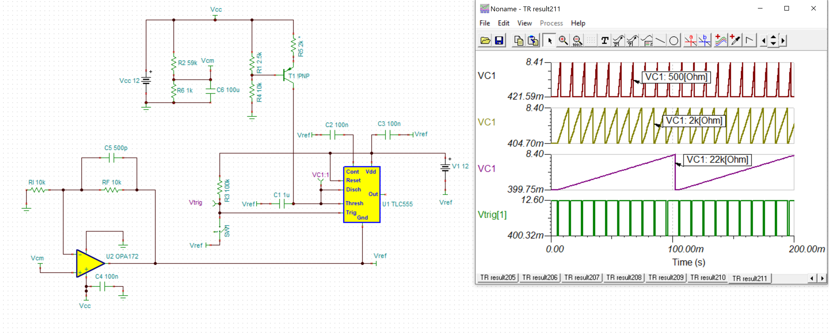
    The ground connection is relative and the TLC555 GND doesn't need to be the same as system GND. I should have connected the bypass capacitor from the power supply to the new "GND" of 400mV. 

    I am currently trying to get my simulation to work, using an amplifier to drive the 400mV. Resistors R23, R6 and C6 were used as a voltage divider with low pass filtering that I intended to set the Vcm of a non-inverting amplifier. This would be used to set the GND connection of the TLC555 to 400mV. I am currently trying this out with the OPA172. I will update shortly with this setup if I can get the simulation to converge. 

    Best Regards,

    Chris Featherstone

  • Hello D.,

    I got the simulation to work with the OPA172 driving the reference voltage to the Gnd pin of the TLC555. It does take a long time to run just so you know if you attempt to run it. I have attached the update Tina file below. You can see the adjustments I made to the reference points, specifically Vref around the TLC555. 

    5861.TLC555 Ramp Generator.TSC

    Best Regards,

    Chris Featherstone

  • Hi Chris,

    thank you for the sim.

    i used OPA197 instead of OPA172, i think this will be ok?

    Also i added a buffer for Vramp and added a MUX to get 8V on output when the ramp finishes, is this approach ok?

    Please find the sim attached.

    RampGenerator_MUX.TSC

    Best Regards,

    David.

  • David,

    Yes, the OPA197 would also be a good choice. I looked over the tina simulation and ran the transient analysis. Good idea on using the mux with the buffer! I haven't found any issues using this approach. 

    Best Regards,

    Chris Featherstone