


Other Parts Discussed in Thread: CDCE6214
Hello,
I need to provide a 322.265625 MHz reference clock to an Intel Cyclone 10 GX FPGA for use with an USXGMII interface. This is needed to communicate with a 10GBASE-T PHY from Marvell.
I'm planning to use the CDCE6214 but I'd like to first obtain a working configuration with the EVM.
I'm performing the measurements on the output waveforms with a RTO2034 from Rohde&Shwarz, 3GHz, 10Gsa/s with an active differential probe with 3GHz of bandwidth for maximum accuracy.
I'm measuring the output of OUT1, configured as LVDS 1.8V. I also soldered the two 50ohm termination resistors (R39 and R43 + 0ohm on R41) on the board in order to obtain the best signal possible.
The CDCE6214 is configured as follows:
- 25MHz crystal on secondary ref.
- Doubler/divider set to /1 -> PFD Freq = 25MHz
- 100uA CP gain and 8.9ns Lock window
- Default loop filter for fractional PLL: Rp=4.5k, Cp=18.72pF, Cz=608.7pF, R3=0, C3=1.2pF
- PLL: Integer=103, Num=10000, Den=80000
- VCO freq = 2578.125 MHz
- PSA = PSB = 4
- OUT1: power=1.8V, source= PSA, divider=2, driver=LVDS 1.8V, Output freq. = 322.265625 MHz
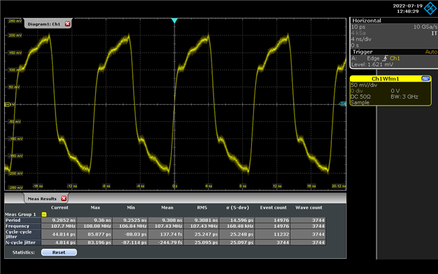
The problem is that I'm measuring about 1.6 MHz of std. deviation on the output frequency, which is a lot!
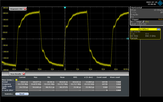
If I increase the output divider (for example I tested the divider = 3, 4, 6 and 12) I see that the shape of the output waveform changes a lot and so does the std. deviation of the frequency. This falls to 43 Khz with the divider = 12.
Am I doing something wrong? Is it normal to obtain this behavior?
Thank you
Output waveform with divider = 2:
Output waveform with divider = 3:

Output waveform with divider = 4:

Output waveform with divider = 6:
Output waveform with divider = 12:
Here's 2 screenshot of TICS Pro with my current configuration:
