This thread has been locked.

If you have a related question, please click the "Ask a related question" button in the top right corner. The newly created question will be automatically linked to this question.

LMK04828BEVM: Output frequency paranoia, and can not output VCO0 frequency point

Part Number: LMK04828BEVM
Other Parts Discussed in Thread: LMK04828

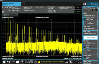
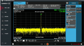
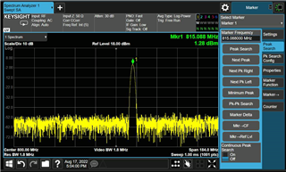
After removing the C4, R3_AB1 and R18 devices and connecting R1 to ensure that the clock of the board is completely powered off, I connected OSCin* and CLKin1* to two 100M 3DBM signals output by the same signal source (which have been calibrated by the spectrum analyzer) and conducted online configuration through TICS PRO. The target requires the output of 2.4g frequency points, but observing the spectrum analyzer, the frequency point of VCO0 cannot be obtained without any frequency. After frequency division, the output clock will be offset. If 1200M is configured, 1222M will be obtained, and if 800M is configured, 815M will be obtained. Do we need to remove the clock CVHD-950-122.88? Or is there another way of thinking about it? DCLKout0 of the output terminal.

  • 2400 GB cannot output normally

  • The 1200M side becomes 1225M

    The 800M side becomes 815M

  • Hi,

    Can you please share your TICS PRO config file?

    Regards,

    Jennifer

  • You can use this configuration file, the board card external two 100M reference clock, do not know can reproduce.

  • Thanks for providing the TCS file.

    Looking through the tcs file, I see that you have the feedback mux enabled, but the prescaler path is selected. The N-Cal divider is also configured incorrectly. Finally, the PFD frequency is configured for 200MHz, which exceeds the maximum available frequency on LMK04828 (155MHz). I would take the following actions first, just to get PLL2 locking:

    • Disable FB_MUX_EN for now - this is only needed in zero-delay configurations.
    • Set the doubler to x1 mode so the PFD max frequency is not exceeded
    • Set the N-divider and the N-Cal divider to 12, so the total division during calibration and during normal operation is 24 (from the 2400MHz VCO).
    • Disable PLL1 (PLL1_PD=1). Since you're driving 100MHz from external source into OSCin, this should be sufficient to get PLL2 working - PLL1 is only necessary when the input reference is noisy, and a VCXO is available to lock the noisy input reference and provide a clean source (potentially at a higher frequency) to PLL2.
    • Configure output clocks for the appropriate EVM termination. I didn't see you mention removing R103 and R111 for DCLKout0, so I configured DCLKout0 for LVPECL instead of HSDS. HSDS can theoretically drive the 240Ω loads in addition to the output impedance, but it will create distortion; LVPECL is the better choice if these resistors are still populated.

    I made the changes in the attached TCS file below. This locks on my board in the lab and gives the expected frequency.

    2.4G_TI.tcs

    As for reworking the EVM, removing R18 should be sufficient to ensure the VCXO is unpowered, so there should be no interference from the on-board 122.88MHz source. You do need to populate R1 for an external signal on the OSCin connectors to drive the OSCin pins; a quick way to do this is to rotate C4 90° and populate it in R1 footprint, to allow single-ended AC-coupling of the new reference on the OSCin* port.

    Regards,

    Derek Payne