


Part Number: LMK03318
Other Parts Discussed in Thread: ADC3669, LMX2571,
Hi,
I have a High speed ADC (ADC3669) which requires 500MHz of clock for sampling at 500Msps of input data
The ADC requires a jitter close or less than 100fs for better SNR
I have two such ADC, recently in some threads TI FAEs have suggested to go for using LMX2571, but i am quite uncomfortable in configuring it due to its complexity and lack of documentation for configuring it for dual output 500MHz clock source for ADCs.
so i have switched to using LMK03318 and disabling unused clocks supply
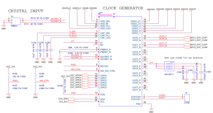
Kindly let me know if my below configuration schematic is to the expectation of meeting the requriement
Clock Configuration
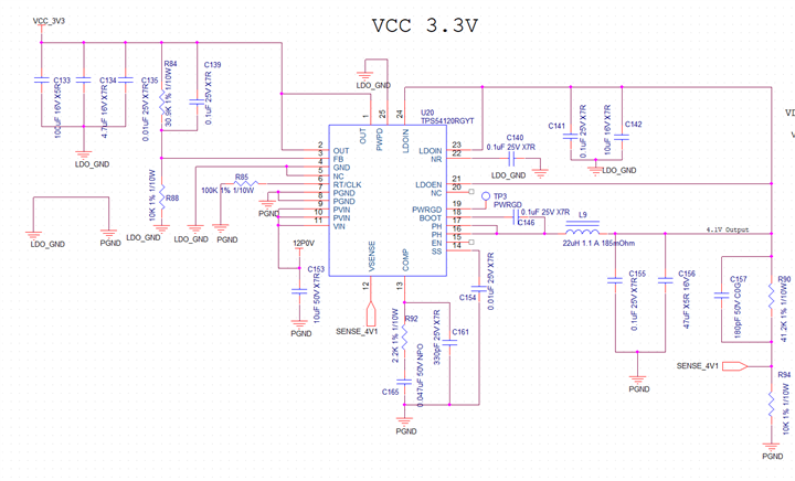
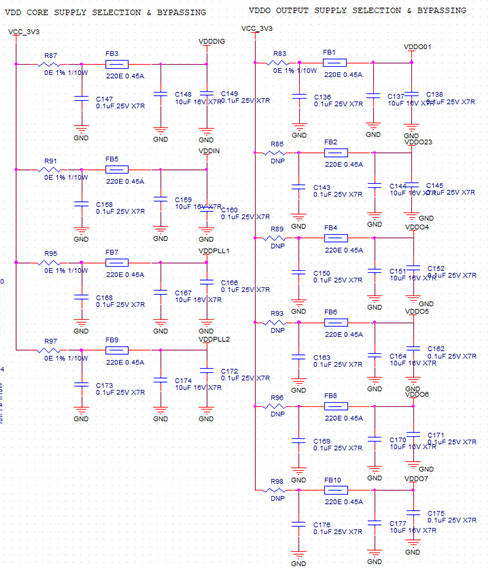
Power supply configuration
My Major Doubts are
1. Are above clock and power configurations correct
2. can i leave un-used clock pins floating ?
3. what is the appropriate capacitor for loop filter for my requirement
4. can a single 50Mhz clock source at secondary source sufficeint to generate two 500MHz clocks parallelly ?
5. what is the register configuration for setting the clock, can i make the settings non-volatile ? so that the clock are default on startup ?

