This thread has been locked.

If you have a related question, please click the "Ask a related question" button in the top right corner. The newly created question will be automatically linked to this question.

LMX2594: SYNC category and phase instability

Part Number: LMX2594

Hi all, 

We referred to the LMX2594 datasheet but are not fully clear on the SYNC category and it’s a necessity to get a stable phase.

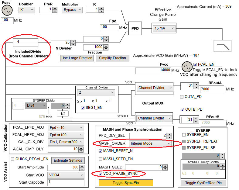
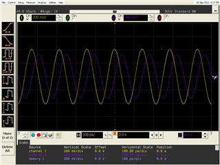
Our Post-R Divider = 1, Channel Divider = 2, reference clock is 100MHz and Fout = 7GHz. As per the flow chart to determine the SYNC category in the LMX2594 datasheet, it points to Category 1 where no software/pin SYNC pulse is required. However, we observe unstable phases over time though we are setting VCO_PHASE_SYNC = 1, INPIN_IGNORE = 1. Do we need to toggle VCO_PHASE_SYNC from 0 to 1 keeping FCAL_EN = 1 additionally?

Kindly suggest on identifying the SYNC category and configuring correct registers.

Thanks

Atul

  • Hi Atul,

    Since you have CHDIV = div/2, even though you are in Cat.1, but SYNC mode is required. That is, you need to make VCO_PHASE_SYNC = 1. Every time you power up the device and program all the necessary registers, RFout and OSCin should be synchronized.  

    Since VCO_PHASE_SYNC = 1, IncludedDivide will be greater than 1, depending on your configuration, you may have minimum N-divider requirement problem and need to adjust the MASH order or phase detector frequency. Suggest use TICS Pro to work out the configuration.

  • Thank you for the quick response!

    We can confirm that we are in SYNC mode 1 (Post-R Divider = 1, Channel Divider = 2, REF clock is 100 MHz and Fout = 7 GHz).

    We are running in integer mode.  We set VCO_PHASE_SYNC = 1 right at the start before any PLL programming and adjust the N-divider values accordingly.  Constraints on N-divider value and CHN_DIV buffer are met.

    We then program all the required registers for setting the output frequency to 7 GHz.

    However if we compare the phase output of two LMX2594s and repeatedly run auto VCO calibration (FCAL = 1) on one of them, when the PLL is locked, we find that occasionally the output phase jumps by ~ 5-8 degrees.  Note the size of the jump appears to be inversely proportional to the N-divider value.

    Now if instead, we repeatedly run FCAL=1, then wait for the PLL to lock, then toggle VCO_PHASE_SYNC = 0 => VCO_PHASE_SYNC = 1, we now appear to achieve consistent phase alignment (no jumps).

    As we are in SYNC mode, we think there should not be the requirement to toggle VCO_PHASE_SYNC to achieve consistent phase.

    Please can we confirm if toggling VCO_PHASE_SYNC is required in SYNC mode 1 or not? It feels like we are missing something!

    Thank you for your assistance!

  • Hi Atul,

    I am pretty sure toggling the VCO_PHASE_SYNC register bit is not necessary, I will try this out on Monday.

    BTW, could you confirm you are using below configuration? If not, please provide your TICS Pro configuration so that I can use it in my experiment. 

  • Hi Noel,

    Thanks for reply. We confirm above configuration, please check it in your experiment once.

    Regards,

    Atul

  • Hi Atul,

    Please allow some time. Noel will get back to you soon.

    Thanks!

    Regards,
    Ajeet Pal

  • HI Atul,

    I checked this out, I didn't see phase misalignment. Once both devices are powered up and programmed, their outputs are phase aligned. I also tried reset one of those devices and then reprogramed it, output phases are again aligned. I was using a board with two LMX2594 on it. https://www.ti.com/tool/LMX2594PSEVM

  • Hi Noel, 

    Thanks for reply! We would like to recreate your experiment at our end using TICS Pro, could you please share all register configurations used by you? 

    We see phase shifts randomly over time like few times within 1 hour, 2 hours or even longer. Could you confirm how many times did you repeat your trials, is it possible for you to run for 100 or 200 runs?

    Regards,

    Atul

  • Hi Atul,

    Here is the TICS Pro configuration, same as the picture I attached in the thread. 

    e2e2594.tcs

    Did you mean, you can get the phases aligned shortly after Vcc power up and programming, but if you left the devices running for some time, their phases changed? This is possible especially if the devices are located at different boards or if they are sitting on the same board but is far away from each because temperature will change the phase. 

  • Hi Noel,

    Thanks for sharing the register configurations, we also tried it on TICKS pro, our registers are not much different.

    Yes, we get the phases misaligned when we keep repeating for some time. We agree temperature variations of few degrees but we see a clear shift of definite degrees and that changes when we tune another frequency, so it seems related to CHN_DIV and N-Divider.

    We will try few experiments as you have done soon. Meanwhile, if you get any clue, please keep posted here.

    Regards,

    Atul

  • Hi Atul,

    FYI, I have the dual PLL board running for a day, the phase difference between them remains unchanged (memory 1 = channel 1 one day ago)

  • Hi Noel,

    Thanks but we are actually testing phase stability when PLLs are power cycled or retuned over time again and again. There are occasional phase jumps for above changes in configurations like CHN_DIV, N-Divider and it remains in that phase state for next few re-tunings and comes to original phase again. So, it's not plain stability of PLLs over time but the consistency of re-tunings over time.

    regards,

    Atul

  • Hi Atul,

    For a fixed PLL frequency in multiple LMXs, phase skew/difference would be the same as Noel mentioned above. 

    If you still see the issue, could be please elaborate more on your actual test setup (setup image or block diagram) for details understanding then can suggest more on the issue?

    Thanks!

    Regards,
    Ajeet Pal