This thread has been locked.

If you have a related question, please click the "Ask a related question" button in the top right corner. The newly created question will be automatically linked to this question.

LMX2594: Quick Sanity Check

Part Number: LMX2594

Hey team,

Quick question on INPIN_IGNORE.. if the following sequence is done, the device will synchronize properly, right? This seems to be how the datasheet explains it as INPIN is only valid while SYNC is 1.

  • We set VCO_PHASE_SYNC=1 and INPIN_IGNORE=0 to enable phase synchronization.
  • We drive the sync input with a periodic signal. So sync is triggered continuously.
  • After a while, we set INPIN_IGNORE=1 right before a rising edge of the periodic sync input, to ensure that no further pulses will have an effect.

Thanks,

Cam

  • Hi Cameron,

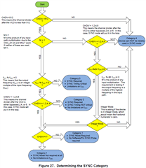
    With Sync Cat. 1, we don't need a SYNC pulse to trigger synchronization, INPIN_IGNORE can be either 1 or 0.

    With Sync Cat. 2 or 3, we need a SYNC pulse, so we need to make INPIN_IGNORE = 0 otherwise the SYNC pulse cannot pass through chip. 

  • Hi Noel,

    What does Sync Cat. refer to here? I'm not following.

    Thanks,

    Cam

  • Hi Noel,

    Quick follow-up question, if you are operating in category 3, is it possible to leave sync as a periodic signal and trigger sync in the LMX2594 wit this periodic signal and then set INPIN_IGNORE=1 before another sync rising edge? In the design, the FPGA can tell when a rising edge of sync is going to happen.

    I guess this is more of a question on your second point - what happens when INPIN is pushed to a 1after a SYNC pulse has been detected?

    Thanks,

    Cam

  • Hi Cameron,

    INPIN_IGNORE bit is used to control the pin function but not SYNC function, we can set this bit = 1 any time we want. 

  • So by setting INPPIN_IGNORE=1 prior to Sync going high, we will effectively ignore the high pulse and the application will perform as the customer expects? Just clarifying for myself.

  • Hi Cameron,

    When INPIN_IGNORE=1, SYNC pulse will be ignored, incoming SYNC pulse is not able to trigger a synchronization.

  • Hi Noel,

    Quick follow-up question..

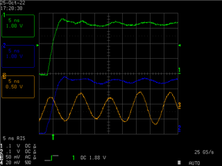
    The input to the sync pins is a continuous 1.95MHz Square wave rather than a pulse, the clock is 93.75MHz, setup and hold of rising edge shown below where green and blue are the sync input and orange is the clock:


    To enable synchronisation I enable then disable the INPIN_IGNORE as fast as I can given the limitations of SPI. The final write is synchronized to the falling edge of the sync waveform:


    Above plot shows the 4 SPI lines plus the sync signal.


    If the LMX output frequency is unchanged then repeated synchronisation, as above, always gives a conistent phase relationship between the two LMX chips outputs (but not necessarily 0 degrees).


    If I now change one of the LMX’s output frequency and then set it back the phase relationship between the two chips will change, but applying the above synchronisation will not necessarily restore the same phase shift as before the frequency was changed. But it will now be consistent at this new value over repeated sync attempts.


    Can the LMX2594 work in this way or is a single pulse mandatory?

  • Hi Cameron,

    Did you use MASH_SEED?

    I expect the phase should be same as before unless heat has alternated the phase difference a little bit.