This thread has been locked.

If you have a related question, please click the "Ask a related question" button in the top right corner. The newly created question will be automatically linked to this question.

LMK04828-EP: Locking issues

Part Number: LMK04828-EP

Hi,

We have developed some PCBs with the LMK04828SNKDTEP. What we observe is some of them lock to an external reference (PLL1) almost automatically, some of them take some more time to lock and some of them don't lock at all.

Some inputs that could be helpful to know:

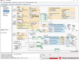
 This is how we configured our LMK

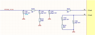
 The external loop filters can be found below

 - An additional behavior we have notice is that we observe some "ageing", i.e, we have some samples we use to lock automatically, then   took some time to lock, then they stop locking again.

- We have notice that some of the samples lock if we relax the digital locking condition, i.e window of 43 ns with 8192 counter to a counter with 768.

We have measured the temperature and we don't seem to excess the maximum ratings of the device.

Could you please orient us about what we could have go wrong?

Best regards,

Manuel.

  • Hello Manuel,

    What seems to not be locking your PLLs over time is your loop filter. From running a simulation, from the values you gave me, it seems that your phase margin is way too low (phase margin = 6.9 degrees), assuming your VCXO gain is 0.0025 MHz/V (TI standard for our EVMs) and you want to keep your loop bandwidth at 60Hz. If so, you should change your C263 = 2.2nF, C262 = 33 nF, R222 = 82 kΩ (phase margin will go up to 70 degrees). I obtained this values by using PLLatinum Sim, which you can download here. I have also attached a picture of my results from PLLatinum Sim below.

    If you would like more help from my end, please include in you reply your external VCXO's gain or data sheet and your desired loop BW.

    Good Luck,

    Andrea

  • Hi, thank you very much for your answer.

    We modify the filter components and now we have more consistency in our PCBs. So definitely this is related with the loop filter.

    We also found a method which works for all boards:

    - first we set PLL1 to work in open loop (forcing holdover mode) and we manually set VCPout1 to 1.65 V

    - We close the loop and PLL1 will lock.

    Just out of curiosity we have the suspicion VCPout1 is not close to 1.65V when we reset the PLLs. Have you experimented with this?

    Manuel.

  • Hello Manuel,

    Could you further explain what you mean by not close values, i.e by how much?

    Do know that if the PLL is locking then VCPout1 must be around of 1.65V; however, the range depends on your VCXO, the accuracy of your reference clock, the temperature being used, etc.

    Thanks,

    Andrea

  • Hi Andrea,

    Yes, we know that.

    However with the method I describe they are all locking independently if we changed the loop filter values or not. I need to measure the exact VCPout1 value after writing the LMK registers.

    Manuel.

  • Hello Manuel,

    The only way you can measure the voltage at VCPout1 is to use a voltmeter and measure the voltage from that node to GND. Once you know that voltage by using the voltmeter, I should be able to help you further. Also, I would like to note that PLL1 will still lock and remain locked even if VCPout1 is not exactly 1.65 V (this is dependent on your VCO).

    Thanks,

    Andrea