This thread has been locked.

If you have a related question, please click the "Ask a related question" button in the top right corner. The newly created question will be automatically linked to this question.

LMK00804B: Input driver for LMK00804B to get 3V/ns otherwise chatter

Part Number: LMK00804B
Other Parts Discussed in Thread: , LMK00804, LMK1C1102, LMK1C1104

Hi,


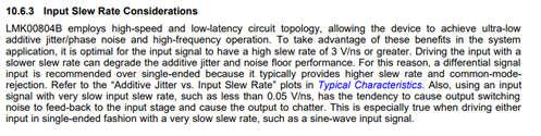
Or the basic question is: Please note the required Input driver (or even parts) for LMK00804B as 3V/ns otherwise chatter O:(


More about my use:


I use the LMK00804B as clock distribution driving from an 0.5/ns OXCO 10Mhz as digital AHC 3.3V output.

The project is a research on Jitter measurements in a different way as seen today.


I see this Chatter clearly at the output using the LeCroy WM8600A at 200G/s, as low frequency flutter or low freq. Jitter.


I like the LMK00804B, as has a synchronized output stop / start. Only missing not having to inputs for clock switching.


Also, did not found any benefits in terms of performance benefit if I would build or connect to the symmetric input buffer.


There is also a new LMK00804B-Q1 as different food print. I means as this chip is equal or any different?


Best regards


Hanspeter

  • Hi Hanspeter, 

    1. Slew rate of 3V/ns is a datasheet recommended condition for optimal performance of the device. For your case the slew rate is about 0.2V/ns (assuming single ended sine wave)  which could cause chatter. There is no minimum slew rate specification in the datasheet but a generalization in below input slew rate consideration section. 

    2. LMK00804B-Q1 would required higher slew rate as well as mentioned in the datasheet.

    Best,

    Asim

  • As 0.5V/ns is from a square wave OXCO output, as 3.3V AHC logic already mentioned and this is never sine output!

    So I ASKED for the required driver IC from TI company, what I did not found or what your engineers recommend, while nothing seen so far even with google ...

    It is so simple... O;)

    Cheers Hp

  • Hi Hp,

    My apologies for missing that critical piece of information there. As I mentioned before LMK00804B-Q1 would be similar to LMK00804. 

    I would suggest to use LMK1C1104 as an LVCMOS output fanout buffer. It has a minimum slew rate spec of 0.1V/ns. 

    Let me know if this answers your question. Could you also share your output waveforms as well for us to take a look into this?

    Best,

    Asim

  • Hi,

    to use it as a front translation buffer I would use the LMK1C1102 ... but specs are for

    fIN = 156.25 MHz, Input slew rate = 2 V/ns, Integration range = 12 kHz - 20 MHz

    The integration range should be much lower to cover may in a separate measurements about any Chatter.

    Currently as looking at DIODES Incorporated as P16C49xxx as more closed in terms of circuit.

    Just funny that all LMK distributions do not provide any (better) application notes on tht Chatt matter even no lower PN down to 1Hz or even lower.

    So TI engineer please...

  • Hi Hans,

    1. Recommendation for LMK1C1104 is due to 10MHz clock with 0.5V/ns slew rate. Since this part has a minimum slew rate spec of 0.1V/ns this would not cause any chatter or glitches on your buffer output than LMK00804B which causes problem at lower slew rates. 
    2. This spec "fIN = 156.25 MHz, Input slew rate = 2 V/ns, Integration range = 12 kHz - 20 MHz" is for best jitter performance at this frequency specified in electrical characteristics table is following widely used requirements for SONET in the industry.  Jitter specs would change for different clock inputs and different slew rate which doesn't mean the part would be chattering at lower frequency with lower slew rate if they are in datasheet specification limits.
    3. Could you elaborate how your are relating the chatter with jitter intergradation band?  Because I would think when your output is chattering, your output frequency won't be expected one on testing equipment (phase noise analyzer ), It might shift so the integration band doesn't matter in that case.
    4. Current  phase noise plot go down to 1KHz in the apps note. Could you tell if you are interested in 1/f noise of it?

    Best,

    Asim

  • As I told already, here again:

    I need the sync output on on/off circuit of the given LMK00804!!!!! SO I ASKED for an input driver!!!!

    Read from may older TI engineer: Bruce Trump @ TI on Chatter so he is may no any longer at TI (now fishing or at the pool)

    Currently the differential input looks as much less Chatter as driving it directly, as without any attenuation's.

    The datasheet is here not very clear on that matter.

    Data sheet LMK00804B /July 2014 as

    - 7.7 Differential Input's as min 2V, max VDD + 0.3V

    - 7.8 as max 1.3V differential!! May this is for operations and requires any input attenuation's!!! Or may only if nClk switching too!

    As I use fixed nClk with additional 1K/1K & Cap as a reference and Clk as the AHC OXCO output and serial resistor.

    Really special for this LMK00804, to get 6V/ns on output as 50E, it requires 3V/ns on input and there is nothing mentioned how the transfer speed(behavior is any better on LVCMOS_CLK compared to the differential CLK & nClk one.

    To use a LMK1C1102 as driver is may an option, but I consider other brands as TI looks like lost/unable in this regard.

    Hp

  • Hi Hp,

    LMK1C1102/4 does have synchronous output disable and enable feature similar to LMK00804B. It also has minimum slew rate of 0.1V/ns values listed in electrical characteristics which makes it good contender to work with your conditions. 

    LMK00804 would cause problem with slower slew rate because if you transition across the switching threshold slowly (i.e. with low slew rate), it takes longer for the internal signals to transition, and they become susceptible to amplitude modulation noise being converted to phase modulation.

    This is less true for differential inputs where common mode noise is rejected, but can still be a consideration.. but for single ended case its a big consideration.

    - 7.7 Differential Input's as min 2V, max VDD + 0.3V

    These conditions as you highlighted above are defined for  CLK_EN, CLK_SEL, LVCMOS_CLK pins.

    - 7.8 as max 1.3V differential!! May this is for operations and requires any input attenuation's!!! Or may only if nClk switching too!

    While using this as single ended this would required some attenuation and dc offset as suggested in termination section below.


    Best,

    Asim

  • Hi Hp,

    There could be couple of solutions as well if the we want to use the LMK00804B. 

    1. We can use LMK1C1104 as input to LMK00804B to achieve higher slew rates. So the setup would be 0.5/ns OXCO 10Mhz > LMK1C110X > LMK00804B.  Since the input slew rate LMK1C110X device is 0.1V/ns it won't have any chatter on output resulting in clean output for LMK00804B. 

    1. Other option could be to use limiting amplifier like ONET1191P to get better slew rates at inputs of LMK00804B.

    Let me know if you have any other concerns related to your query.  

    Best,

    Asim