This thread has been locked.

If you have a related question, please click the "Ask a related question" button in the top right corner. The newly created question will be automatically linked to this question.

LMK04610: LMMK04610: PLL1 fails to lock to a reference input which is negative in ppm

Part Number: LMK04610

Hi,

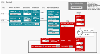
I am facing issue with PLL1 locking to a reference input which runs negative in ppm to the current holdover clock (or the previous reference input).
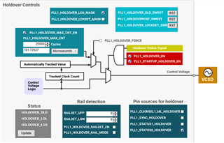
Image below shows my input and PLL1 and holover configuration, I am using holdover feature where PLL1_HOLDOVER_LCKDET_MASK is unticked to make sure that the device switch to holdover upon PLL loss lo lock.

The device is comfortably entering in to the holdover up-on an LOS or ppm changes triggered from tester.

For any positive ppm changes at the input clock, the PLL1 is able to lock once I set the PLL1_HOLDOVER_LOCKDET_SWRST to initiate the reset from holdover.

But for many a times for any negative ppm change from the tester, PLL1 is unable to lock to the reference even after the PLL1_HOLDOVER_LOCKDET_SWRST is set even after getting the input clock to a stable (a negative ppm change)

As shown in the image below, I have enabled the PLL1_LOL_NORESET.

The PLL1_RC_CLK_EN flag is Disabled. Can you please let me know what is this feature about?

Kindly review and suggest on what could be going wrong in my configuration or system.
Thanks,

Vinod

  • Hello Vinod,

    To double check it's not a problem with the VCXO, could you check the Vtune voltage with the same positive ppm and negative ppm magnitude? If the voltage difference between the two frequency deviations is pretty close and PLL1 is still not locked, then it is a problem with the VCXO tuning range. Make sure to turn off holdover mode when you test this.

    Thanks,

    Andrea

  • Hello Andrea,

    Thank you for the response and guidance.

    I have checked on the VCXO response with holdover disabled. At 0ppm input clock, the voltage read 1.572v and when I reduced the input clock by 1ppm (-ve), the voltage at VCXO changed to 1.562v. For a -10ppm change it ended up at around 1.472v. PLL1 continued to be out of lock for most of the times, but I could see that at times the PLL gets locked but immediately loses it and it continue to flicker the state between lock and out of lock (may be "locking").

    Now, keeping the Holdover disabled, I un-ticked the PLL1_NO_RESET option and could see that the PLL is getting locked for both +ve and -ve ppm movements.

    When the holdover was enabled, I used to follow the sequence of writes through s/w to bring it out of holdover.

    1. Write 0x57 with 0x2

    2. Write 0x57 with 0x19

    3. Write 0x57 with 0x11

    4. Write 0x57 with 0x1

    As you can see, the sequence also had a PLL1 SW RST sequence in it, but even with that included I was not getting PLL locked for the same -ve PPM change at the input.

    I doubt if the device is entering holdover as soon as an attempt is made to lock to the new  -ve ppm and immediately gives up and goes back to holdover.

    I am little confused if to disable holdover and keep PLL1_NO_RESET unticked to get this working, though I am not gaining much with holdover enabled other than expecting some better timing when locking to a new clock as it doesn't move so away from the old reference.

    Kindly check and let me know your valuable suggestions.

    Thanks,

    Vinod

  • Hello Vinod,

    I will get back to you by Monday PST.

    Thanks,

    Andrea

  • Hello Vinod,

    Figuring out a solution is taking me a little bit longer than expected. I will try to answer your question by Wednesday PST. Thank you for understanding.

    Best,

    Andrea

  • Hello Vinod,

    First off, it's important that you check the PLL1_HOLDOVER_LCKDET_MASK if you want that value to be 1. When PLL1_HOLDOVER_LCKDET_MASK = 1, then lock detect has no effect in activating holdover (I'm assuming you want holdover only when a LOS event occurs, not on lock detects). This should then only activate holdover if you end up having a LOS and that way the reference won't move away too far from the old reference. 

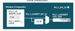
    Also, PLL1 DLD will report unlocked whenever you are outside a specified window for a certain amount of times, and your window size is too small with a 1.2288 MHz f_PD and counter size is too big. If you use the information in p. 116 of the data sheet, you'll see that your minimum lock time is at least 3s, which is too high, and your ppm is basically zero. Note that your counter ends up being 32 x 115200 = 3686400 because you have PLL1_LCKDET_BY_32 ticked.

    My suggestion is to make the window size 40ns and your counter size 9830 with PLL1_LCKDET_BY_32 ticked.

    Good Luck,

    Andrea

  • Hello Andrea,

    Thank you for coming back.

    In the beginning of my project, the configuration was with PLL1_HOLDOVER_LCKDET_MASK = 1 and the scheme was solely depending on the LOS.
    Also the window size and the counter size were 40ns and 16356 respectively.
    With this we were getting the PLL1 lock fast but PLL1+PLL2 combined was taking a longer time to achieve the frequency lock (to the required ppm tolerance of ~2ppb) to the input reference clock.
    By this time, the link partner was reporting link up and soon going down as it see too many errors in the serdes since the clock used for our transmit not being stable.
    This would again cause a link down event at our end and this would happen in a loop.

    To mitigate this issue we have done two changes in the settings according to the suggestions from TI.
    First one, see the response below:

    ******************************************************************************************************************

    I believe, the LMK04610 has an issue to enter in holdover mode using the LOS_EN, as there may be recovered signal but PLL1 is taking long time for lock with the recovered signal.
    You can try with the PLL1_DLD enable (PLL1_HOLDOVER_LCKDET _MASK -> 0) to enter in holdover and it jumps to the holdover mode once, it sees the PLL1 is unlocked (PLL1 LD = 0).

    ******************************************************************************************************************

    Also the suggestion was to make the ppm stringent to get it stable.
    After doing these changes the clock was stable enough for the link partner to get the data error free and declare stable link-up.

    Now, your suggestions are precisely asking me to revert the changes which I think won't work well with me.
    I have following questions on your suggestions,

    1. What is the penalty on clock output ppm if we relax the PLL1 window comparator?

    2. What will be the Vc control voltage output from PLL1 to the VCXO when the PLL1 is put under reset due to a LOL event?
       This is to understand if I can go with holdover disabled as the holdover is not serving any purpose in my system.

    Let me know your suggestions.

    Thanks,
    Vinod

  • Hello Vinod, I'll get back to you by the end of this week. Thank you for your patience.

    Best,

    Andrea

  • Hello Vinod,

    Please find the answer to your questions below:

    1) By relaxing the PLL1 window comparator, that means the PLL is given a smaller error window for the PLL to say the frequencies are closed enough and consider them locked. Therefore, this will lead the PLL to take a longer time to lock and hence a longer time for the clock outputs to be displayed as correct. Overall, the smaller the ppm, the longer it'll take for the outputs to be the desired frequencies; the bigger the ppm, the faster the outputs will be at the correct frequencies.

    2) When no holdover is present and a LOS event occurs, the reference signal becomes 0, which it'll lead the PLL to attempt match that 0 Hz frequency. Because of the frequency range limits the VCO has and the frequency of 0 Hz always following out of that range, the PLL will never lock. This will lead to Vc to be either 0 V or Vcc (depending if your VCXO gain is positive or negative).

    I hope this answers your questions.

    Best,

    Andrea

  • Hi Andrea,

    I would like to get a little more clear on the following..

    " Overall, the smaller the ppm, the longer it'll take for the outputs to be the desired frequencies; the bigger the ppm, the faster the outputs will be at the correct frequencies."
    [Vinod:] Does this mean that the output frequencies that are derived out of PLL2 synthesizer will be at the required ppm tolerance (stringent requirement of <10ppb) faster when the PLL1 ppm is kept wider? What is the relation of output clock stability of the PLL2 synthesizer in terms of ppm to the PLL1 ppm lock setting?

    "This will lead to Vc to be either 0 V or Vcc (depending if your VCXO gain is positive or negative)"
    [Vinod:] I assume this would mean that a longer time for the clock lock will be the penalty here as well.

    Thanks,
    Vinod

  • Hello Vinod,

    I will get back to you later.

    Thanks,

    Andrea

  • Hello Vinod,

    Does this mean that the output frequencies that are derived out of PLL2 synthesizer will be at the required ppm tolerance (stringent requirement of <10ppb) faster when the PLL1 ppm is kept wider?

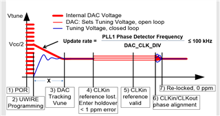
    No. The time that it takes to reach the desired frequency (x in picture below), is not dependent in window size or lock count; therefore, the output frequencies are not necessarily at <10 ppb from the reference frequency since PLL1 ppm's speed is determined by those to variables.

    What is the relation of output clock stability of the PLL2 synthesizer in terms of ppm to the PLL1 ppm lock setting?

    There is no relationship between the clock stability and PLL1 ppm lock setting. Lock settings are derived from the window size and lock count variables, so for instance, if you increase the window size, your PPL1 will lock faster since you are increasing the range of how close to the reference PLL1's feedback signal needs to be. Therefore, with a very wide window size you could be in lock but that doesn't mean your clock outputs are stable. In the picture above, if the peaks of the oscillation fall within the window, that means PLL1 is locked (or following PLL1ppm lock setting), but your signal is not stable since it is oscillating.

    I assume this would mean that a longer time for the clock lock will be the penalty here as well.

    Assuming you do turn holdover off and the signal is lost but then regained later on, that would be correct. Because you are either coming 0 or Vcc, it would take longer to reach the correct frequency as compared if coming from the holdover tuning voltage (which would be closer to the desired value).

    Hope this helps.

    Good Luck,

    Andrea