Because of the holidays, TI E2E™ design support forum responses will be delayed from Dec. 25 through Jan. 2. Thank you for your patience.

This thread has been locked.

If you have a related question, please click the "Ask a related question" button in the top right corner. The newly created question will be automatically linked to this question.

Jitter Analysis: Spread Spectrum Clock

Hi!!

I am evaluating the performance of our internal PLL.

We are expected to measure the “additional” Jitter introduced by the spread-spectrum clock.

Generally, a clock with Jitter is: Fundamental_Frequency + Error.


The following waveform shows a ~1.15GHz clock with 100KHz SSC modulation – you can see that the waveform is frequency modulated and it moves across time – this periodic movement is what I would call as Desired Jitter.


With SSC modulation enabled, the PLL is going to induce an error, i.e., the modulated clock = Fundamental_Frequency +/- Modulation_shift (or periodic movement or Desired Jitter) + Error.

We intend to measure this Error.


This activity is to quantify how our PLL performs when it is enabled with SSC.

Awaiting guidance on this.

Best Regards,

Kumaran Anand B

  • Hi,

    What is the figure of merit you are wanting to measure for your PLL?  Are you wanting to confirm 100 kHz modulation?

    I suggest using a spectrum analyzer in max hold mode set center frequency to ~1.15 GHz with span of say 300 kHz.  Max hold displays holds the maximum power measured, so you should see some flat top form.

    73,
    Timothy

  • Hi Timothy,

    no, it is not the modulation we want to confirm. I haev already validated the modulation with "Freq vs Time" trend (in Oscilloscope) and Spectrum Analyzer. I am more interested in additional-jitter induced in the output clock because of the modulation.

    The jitter, oscilloscope measures, usually is both the additional-jitter and desired-jitter (the periodic shifts created by the frequency modulation itself). I am interested to know this additional-jitter. We are okay with Periodic Jitter or Deterministic Jitter.

  • Hi Kumaran,

    If you measured with a phase noise analyzer such as an E5052, then this SSC noise would show up as a spur.  You could measure the jitter with the spurs, then you could then turn off spurs from displaying and see what the jitter is and take the difference.

    But you have to be a bit aware.  Typically clocks are measured with for RMS jitter, this is the random component.  It is often measured for some given integration range such as 12 kHz to 20 MHz.  Spurs are deterministic jitter.

    In time domain...

    Here's an equation of converting spur power to deterministic jitter pk-pk.  DJSPUR (ps pk-pk) = [2 × 10(dBc/20) / (π × fOUT) × 1E6], where dBc is the SPUR level (in dBc from frequency domain) and fOUT is the output frequency (in MHz).

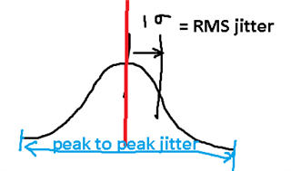
    Note, below is an image which shows that RMS jitter is the standard deviation of the histogram of actual 0-crossing.  A perfect clock would cross at the expected red line every time.  Note that peak-to-peak jitter as measured with oscilloscope will continue to increase due to RMS noise with more samples.

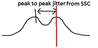
    Jitter from SSC would result in two peaks.  I'm noting this with down-spread from base clock.  This peak to peak jitter would not increase.  If you wanted to understand from a simple perspective how the jitter in terms of 0-crossing would impact your clock, you might say it is jitter = (0.5 * SSC peak to peak + RMS).  Even with the SSC turned on, I think you could make the measurement of the standard deviation of the 0 crossing from the high or low slope.

    73,