This thread has been locked.

If you have a related question, please click the "Ask a related question" button in the top right corner. The newly created question will be automatically linked to this question.

LMX2594: How to align sysref clock between LMX2594 when need to realize multi-chip synchronization?

Part Number: LMX2594
Other Parts Discussed in Thread: TIDA-01021, LMK04828, ADC12DJ3200

Hi, 

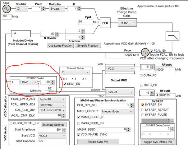
I have a question about alignment of sysref clock  for two LMX2594 which need to realize multi-chip synchronization . My setup is listed below figure1 shown:

  • OSCIN of two lmx2594 are provided 100MHz reference clock from very-low skew clock buffer
  • SYSREFREQ of two lmx2594 are held high so as to work at "Master -Continuos" mode
  • RFAout of two lmx2594 output 10GHz RF clock
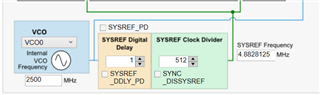
  • RFBout of two lmx2594 is selected to Sysref Clock which output 4.8828125MHz clock for JESD204B

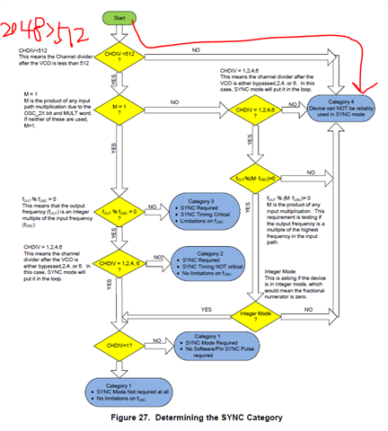
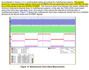
As below figure2 shown, LMX2594 will work at Category1 for RFAout, that means the 10GHz RFAout will align with 100MHz OSCIN. Figure3 show that alignment of 100MHz OSCIN between two lmx2594. So the RFAout of two lmx2594 will align with each other if the 100MHz OSCIN of two lmx2594 will align with each other at the Pin location.  But, the sysref clock of two lmk2594 don't align with each other as below figure4 shown. 

How  could I align sysref clock between LMX2594 when need to realize multi-chip synchronization? 

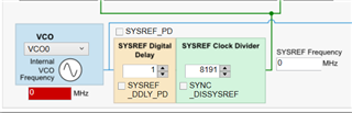
Or, programming the  JESD_DAC1_CTRL, JESD_DAC2_CTRL, JESD_DAC3_CTRL, and JESD_DAC4_CTRL words to realize alignment as figure5 shown?

Figure1

Figure2
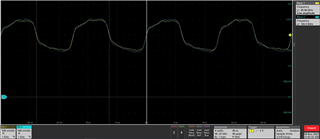
Figure3

Figure4

Figure5

Best regards!!!

Jason

  • Hi Jason,

    When the LMX2594 is operating in SYSREF generation mode in multi-device sync, SYSREF dividers act same as channel divider and need to follow the "SYNC category diagram", shown below:

    For SYSREF frequency - 4.8828125MHz and OSCin frequency - 100MHz, the sync comes in CAT-3 (neglect the division value) and it requires the external SYNC, which also the time critical and follow the section 7.3.10.3 in datasheet for sync procedure.

    Thanks!

    Regards,

    Ajeet Pal

  • Hi, Ajeet Pal:

    Nice to meet you again!

    But I see that SYSREF divider is 2048(4x2x128x2=2048),  does the sync mode should come in CAT-4 as below figure.1 and 2 shown?  Why you said CAT-3 above?

    BTW, I check the TIDA-01021 design( Multichannel JESD204B 15-GHz Clocking Reference Design for DSO, Radar, and 5G Wireless Testers) as below figure.3 shown. The two LMX2594 generated the  edge-aligned 25MHz SYSREF. How could  achieve this?  Which sysref mode, repeat mode or master continue or Pulse mode are selected?

    figure.1

    figure.2

    figure.3

    Best regards!!!

    Jason
  • Hi Jason,

    The SYNC category flow chart is made to consider the channel divider values, but when look for the SYSREF in generation mode, their divider values are different and should be sync in a same way as channel divider. So consider the SYSREF divider value passing the first step. Then while reaching to 3rd step (fout%fosc), it is not satisfying the condition for fsysref % fosc (4.8828125MHz % 100MHz ≠ 0), Hence SYNC moved to Cat -3, which requires the external sync and it is time critical for synchronization. 

    Regarding the TIDA-01021 sync performance, seems the above plots are with external sync input in pulsar mode (which is generating from on-board LMK04828) and resetting the DCLK (3GHz) and SYSREF (25MHz) output dividers.

    Thanks!

    Regards,
    Ajeet Pal

  • Hi,Ajeet Pal:

    Get it. Your reply is very helpful for me, thank you very much!!!

    I just read a thread posted 4 years ago as below link shown, which mentioned that "there's no definite phase relationship between the sysref out  and the sync signal". So I have a little worry about whether SYNC can work as your said above. But I will try it, and use SYNC signal to sync two LMX2594 which work at master continue mode. 

    Maybe the LMX2594 have been updated after 4 years and produce usable SYSREF in deterministic lantency.

    https://e2e.ti.com/support/clock-timing-group/clock-and-timing/f/clock-timing-forum/744031/lmx2594-sysref-out-can-not-be-synchronized

    Best regards!

    Jason

  • Hi Jason,

    The statement in the above mentioned e2e thread is by the user, who were not able to get the SYNC.

    But, if you have the timely controlled external SYNC, it would reset the dividers in both LMX at the same time and should give the aligned SYSREF outputs.

    Thanks!

    Regards,
    Ajeet Pal

  • Hi,Ajeet Pal:

    The LMK04828B should produce SYNC event to reset the divider in the LMK04828B itself firstly. Is SYNC event positive edge or negative edge?

    Best regards!

    Jason

  • Hi Jason,

    The SYNC event should be positive edge and should meet the setup and hold timing for SYNC.

    Thanks!

    Regards,
    Ajeet Pal

  • Hi,Ajeet Pal:

    The SYNC from LMK04828B to two LMX2594 does take effect  as below figure shown. After power up, I could see one time of  phase adjustment between sysref clock of two LMX2594 definitely. But, the skew between them is ~80ps.  The reference design of TIDA-01021 could get <10ps clock skew. 

    So, could you please give me some suggestion which aspect could I try to reduce the skew between sysref cloclk?

    Thanks in advance!

    Best regards!

    Jason

  • Hi Jason,

    ~80ps skew could be because of part to part delay variation and measurement error (cable delay variation). This can be further reduced by using the MASH SEED, which would provide the delay in one device and can achieve low skew. You can follow the section 7.3.11 and 7.3.12 in LMX2594 datasheet for precise phase adjustment in the clock out.

    If you are getting the deterministic skew, it doesn't necessary SYSREF delay for fine delay adjustment.

    Thanks!

    Regards,

    Ajeet Pal 

  • Hi, Ajeet Pal:

    All through the SYNC signal from LMK04828B to two LMX2594 has aligned the 4.8828125MHz sysref clock output of two LMX2594(master continuous mode), the phase difference between the sysref clock from LMK04828B to FPGA(yellow curve) and sysref clock from LMX2594 to ADC(blue curve) is not constant as below figure2,3 and 4 shown.  But the phase difference will be maintained in the range of 57~66ns.

    I have synced the sysref divider by toggling the SYNC_POL bit in the LMK04828B firstly, so the sysref clock to FPGA and SYNC to LMX2594 will have constant phase relation.

    My question are  

    1. Why sysref clock have unconstant or small variational phase relation between  FPGA and ADC?

    2. Is the last Channel-to-Channel Skew Measurement(time difference of  between two ADC12DJ3200) of TIDA-01021 select master continuous mode for LMX2594 as figure5 shown?  if yes, is it have the same question with above queation1?

    3. Could repeat mode of LMX2594 output sysref clock  of constant phase relation with  sysref clock to FPGA ?

    Thanks in advance!

    figure1

    Figure2 about 66ns

    Figure3 about 63ns

    Figure4 about 58ns

    Figure5

    Best regards!

    Jason

  • Hi Jason,

    My question are  

    1. Why sysref clock have unconstant or small variational phase relation between  FPGA and ADC?

    Generally for the JESD link establishment, SYSREFs to data converter and FPGA doesn't necessary to be phase aligned but Clocks and SYSREFs to ADC & FPGA clock and SYSREF to FPGA should be phase aligned and meet the setup and hold time respectively. 

    So in your above setup, ADC SYSREF and FPGA SYSREF not necessary to phase aligned (I would recommend to clarify with data converter team once).

    I have synced the sysref divider by toggling the SYNC_POL bit in the LMK04828B firstly, so the sysref clock to FPGA and SYNC to LMX2594 will have constant phase relation.

    LMK04828 SYSREF has common divider so all SYSREFout will be aligned but the device should generate the deterministic phase alignment between DCLKout and SYSREF. Hence need to be reset all used clock out dividers using SYNC_POL (SYNC_DISSYSREF & SYNC_DISx).

    2. Is the last Channel-to-Channel Skew Measurement(time difference of  between two ADC12DJ3200) of TIDA-01021 select master continuous mode for LMX2594 as figure5 shown?  if yes, is it have the same question with above queation1?

    In TIDA-01021 reference design, LMK04828 generating the constant phased aligned outputs and LMX2594 generate the SYSREF in generator mode after resetting the dividers, Where LMX2594 OSCin reference frequency (phase detector frequency) is same as SYSREF frequency. 

    3. Could repeat mode of LMX2594 output sysref clock  of constant phase relation with  sysref clock to FPGA ?

    LMX2594 in the SYSREF repeater mode, re-align the SYSREF output with the interpolator and still can have a contant phase if LMK04828 all outputs are aligned/deterministic phase.

    Thanks!

    Regards,

    Ajeet Pal

  • Hi, Ajeet Pal:

    I know that SYSREFs to data converter and FPGA doesn't necessary to be phase aligned, but they must have constant phase difference during every power cycle . So that LMFCs of data converter (TX) and FPGA(RX) could keep constant phase relationship between them as below figure shown(mark red curve). That is requirement of JESD204B. 

    My original understanding is  that: 

    1. Reset SYSREF divider in LMK04828B by using toggling SYNC_POL, which make phase alignment between SYNC(8 pulses of 4.8828125MHz  )to  LMX2594 and 4.8828125MHz continuous SYSREF clock to FPGA.

    2. SYNC from LMK04828B reset the divider in the LMX2594, so that this SYNC signal have deterministic phase delay with the SYSREF clock out from LMX2594

    3. At the last , 4.8828125MHz continuous SYSREF clock to FPGA have deterministic phase delay with the SYSREF clock  from LMX2594 to ADC

    But,  what I can see is that step.3 don't happen. During  many times power cycle, I found that a small range variation(57~66ns) of phase difference as above my post shown. So, I don't understand why it happen.  Could you please duplicate the similar test on your side?

    Thanks in advance!

    Best regards

    Jason

  • Hi Jason,

    In your setup the LMK04828 SYSREF divider is resetting irrespective of OSCin input using the internal SYNC toggling, which may create different phase between OSCout and SYSREFout in each power cycle. And this different phase SYNC input to LMXs, resetting the SYSREF divider which is showing the phase difference between FPGA SYSREF and ADC SYSREF.

    I would suggest to try the LMK04828 in SYSREF zero delay mode, where SYSREF divider reset is not random and there is a constant phase between LMX2594 OSCin and SYNC input.

    Thanks!

    Regards,
    Ajeet Pal

  • Hi, Ajeet Pal:

    I also notice the 0-delay PLL mode in Channel-to-Channel Skew Measurement of TIDA-01021 , but  I don't know its intention at that time and deem that toggling SYNC_POL is enough.

    So, your meaning is that toggling SYNC_POL to reset SYSREF divider must work together with 0-delay SYSREF mode in the LMK04828B, right?

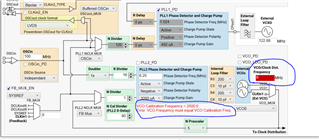
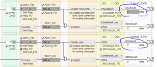
    I try to configure LMK04828 in SYSREF zero delay mode, but it isn't successful in the TICS pro GUI as below figure shown:

    Figure.1 is the previous single loop version, which is normal mode. when I set mode to 0-delay sysref mode as Figure.2 shown, I can't change VCO frequency(Warning will appear). Many setting filed are combinative together, and can't be changed separately.

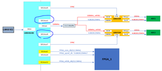
    So, could you please help me generate a .tcs file which realize the clock configuration as below figure.3 shown? 

    Many thanks to you!!!

    Figure.1 the previous single loop version

    Figure.2 single loop 0-delay sysref mode

    Figure3  clock configuration

    Best regards!

    Jason

  • Hi Jason,

    I'll get back to you on this soon.

    Thanks!

    Regards,

    Ajeet Pal

  • Hi Jason,

    The above clocking architecture required to have LMK04828 OSCout frequency and SYSREF out in-phase / deterministic phase. But due to random reset of SYSREF dividers, these are not aligned and shows the phase difference between LMX2594 SYSREF and LMK04828 SYSREF outputs.

    You can follow the multi-clock SYNC app note, which shows the conditions for ZDM.

    If there is no phase noise / jitter critical clocks out from LMK04828, you can use it in ZDM, where PLL2 phase detector frequency should be min. output frequency and should be integer division of OSCin frequency. 100M%4.8828125M is not integer. Hence, I tried to change it to nearby frequency (please verify with your required SYSREF frequency) 6.25MHz and created the LMK04828 configuration file FYR.

    LMK04828_100MREF_PLL2_6.25MSYSREF_ZDM.tcs

    Please use the same and let me know your comments.

    Thansk!

    Regards,
    Ajeet Pal

  • Hi, Ajeet Pal:

    Thank for your support, and I appreciate your great patience!!!

    When I load .tcs file you send to me,  find that VCO don't show any frequency and warning appear too. At the same time DCLKout and SDCLKout also don't have frequency value. Is that OK?

                                                                                               Figure.1

    About  clocking architecture, I have last three questions:

    1.   As to below architecture1(Figure.2 show), for getting deterministic phase between LMX2594 SYSREF output  and LMK04828 SYSREF output, toggling SYNC_POL to reset SYSREF divider in the LMK04828B must work together with 0-delay SYSREF mode , right?

                                         Figure.2

    2. As to below architecture2, LMX2594 work at repeat mode(Figure.3 show, LMK04828B output sysref clock to LMX2594),   will it have the same problem? (undeterministic phase between LMX2594 SYSREF output  and LMK04828 SYSREF output)

                                         Figure.3

    3. As to below architecture3 (Figure.4 show), the OSCin of LMX2594 come from DCLKout of LMK04828B. For this architecture,  toggling SYNC_POL to reset SYSREF divider in the LMK04828B is enough and 0-delay SYSREF mode is unnecessary, right?

                                          Figure.4

    Best regards!

    Jason

  • Hi Jason,

    When I load .tcs file you send to me,  find that VCO don't show any frequency and warning appear too. At the same time DCLKout and SDCLKout also don't have frequency value. Is that OK?

    Ideally while loading the config (.tcs) file, it will update all fields. but if it shows 0 (not sure why), I would suggest to write the correct value of VCO (2500), it will correct all frequencies, as other settings are written properly.

    As I mentioned in previous comment, 100M (LMK04828 OSCout / LMX2594 OSCin) and 4.8828125M (FPGA SYSREF / SYNC to LMX2594) are not integer multiple and their phase can't be aligned at every instance (can probe in oscilloscope), hence seeing the phase issue between LMK04828 outputs as well as between LMX2594s SYSREF out and LMK04828 SYSREF out.

    I would suggest to perform the frequency planning and update the SYSREF frequency as integer division of 100M to achieve phase determinism between ADC SYSREF and FPGA SYSREFs. 

    All above 3 architectures would work, if the frequencies correction done.

    Thanks!

    Regards,
    Ajeet Pal

  • Hi, Ajeet Pal:

    I couldn't change 4.8828125M due to the some limitation of ADC. But I can change 100MHz to 78.125MHz, and 78.125M%4.8828125M is an integer(16). I update the architecture as below figure shown:

    The architecture in Figure1 shown need toggling SYNC_POL to reset  SYSREF  divider  + 0-delay SYSREF mode in LMK04828B to get  deterministic phase between LMX2594s SYSREF out and LMK04828 SYSREF out, right?

                                      Figure.1

    But architecture in shown Figure2 only need toggling SYNC_POL to reset  SYSREF and DCLK divider in LMK04828B to get  deterministic phase between LMX2594s SYSREF out and LMK04828 SYSREF out, right?

    Because toggling SYNC_POL to reset  SYSREF and DCLK divider make the 78.125MHz DCLKout to LMX2594 and 4.8828125Mhz SDCLK to FPGA have deterministic phase relation

                                        Figure.2

    Best regards!

    Jason

  • Hi Jason,

    The change in OSCin frequency should also be fine, where all clocks are integer multiple.

    As mentioned above, if LMK04828 feedback signal is SYSREF frequency (anyways phase detector frequency reduced, which degrades the jitter performance), it doesn't needed SYNC_POL and provide the aligned / deterministic phase outputs. I believe, there is no phase noise / jitter critical clocks out from LMK04828 in architetcure-1 and should be OK. Below is the updated config file FYR.

    LMK04828_78.125MREF_PLL2_4.8828125MSYSREF.tcs

    Regarding the architetcure-2, if you still feedback the SYSREF, it doesn't needed SYNC_POL but DCLKout4/6 outputs phase noise affect, which degrades the LMX2594 performance. Otherwise keep higher phase detector frequency (no SYSREF feedback) and provide the SYNC_POL to aligned all LMK04828 clocks outputs.

    Thanks!

    Regards,
    Ajeet Pal

  • Hi, Ajeet Pal:

    Get itSmile. Now, I have clear understanding completely. 

    Many thanks for your great patience !!!

    Best regards!

    Jason

  • Hi, Ajeet Pal:

    Get itSmile. Now, I have clear understanding completely. 

    Many thanks for your great patience !!!

    Best regards!

    Jason

  • Hi, Ajeet Pal:

    Get itSmile. Now, I have clear understanding completely. 

    Many thanks for your great patience !!!

    Best regards!

    Jason