This thread has been locked.

If you have a related question, please click the "Ask a related question" button in the top right corner. The newly created question will be automatically linked to this question.

CDCE18005: Internal Termination

Part Number: CDCE18005


Hi,

Good Day.

The customer would like to switch on the internal termination at the primary input in order to have a common mode voltage of 1.2V since they are AC-coupling the clock externally.

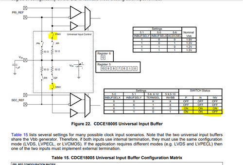
Does bit 9, register 5 (PRIINVBB) have to be set to 0 or 1? According to Table 15, need to be set to 0. Is that correct? Please confirm.

Does this result that the VBB voltage being connected to the positive as well as to the negative input pin?

Thank you very much.

Best Regards,

Ray Vincent

  • Hi Ray,

    Register 5 bit 9 should be set to 0 if we want to connect VBB to both positive and negative input.

    If we just want to bias negative input, then it should be set to 1. Below diagram shows its working.

    For termination scheme, we can follow Table 15. VBB will be connected to both positive and negative inputs based on configuration in table.

    Best,

    Asim