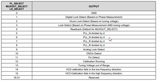
LD_SELECT can be values from 0 to 15. For number 4, READBACK, you have to clock out the bits for the register you are reading. It appears other bits are just a single logic output such as for LD_SELECT values of 1, 2, or 3 that are the lock det functions. For logic detection functions I assume these outputs change with the state of the phase lock and once setup don't require further programming in the synth. These then just become a logic output that can be read by a processor. For values of LD_SELECT from 5 through 15, what is the format of the output in those cases? I assume 5 through 8 have to be clocked out to read a number while 9 through 15 are a simple logic output? Can you share what the format of each of these will be?
Charles L