This thread has been locked.

If you have a related question, please click the "Ask a related question" button in the top right corner. The newly created question will be automatically linked to this question.

LMK5B33414EVM: Help for First start-up and heat development

Part Number: LMK5B33414EVM
Other Parts Discussed in Thread: LMK5B33414
Hello,
I need a reference clock of 10 MHz with the lowest possible jitter for a laboratory and I don't have a lot of experience in programming clock products.
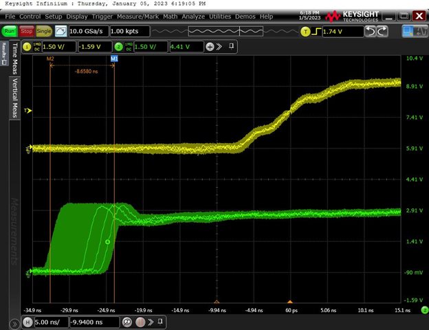
As a reference I use the Ublox ZED-F9T. My measurements has shown that frequencies based on integer dividers of 128MHz have the lowest jitter (+/- 0.4 ns).
All other frequencies show a jitter of +/- 5 ns and correspond to the data sheet.

The Ublox ZED-F9T can be set to frequencies <25 MHz. The duty cycle can be set to e.g. 50%.

It would be very helpful for me at the moment, if I could get a TICS-Pro configuration file.
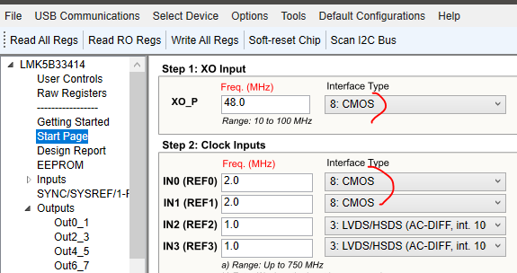
I use the LMK5B33414EVM board. The clock from the ZED-F9T is fed in at IN0_P and has an amplitude of 3.3 V.

It would be very helpful for me at the moment to have a configuration file with 1PPS and a configuration file for a fixed frequency (e.g. 1 MHz) fed in at IN0_P.

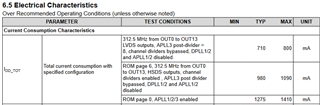
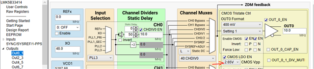
I have another question about the heat generated by the LMK5B33414 chip. I have successfully generated some frequencies at OUT1 and OUT 2 for a first function test. I configured these outputs as "CMOS 2.65-V, P/N = On". I deactivated all other outputs. The chip hardly heats up with this configuration. The data sheet (SNAS835 – SEPTEMBER 2022 Page 23) describes that in the HCSL output configuration, the outputs must each be terminated with 50 ohms. I followed that and also configure another output to HCSL 750mV. As soon as I write this configuration into the board, the chip gets very hot. I felt the temperature with my finger and have the impression that a heat sink is necessary. Due to the heat development, I preferred not to configure any additional output in order not to damage the chip. I saw that there are shunt resistors that can be switched on the board to determine the current consumption. I haven't done any further measurements yet. Is this heat development normal, or have I done something wrong ?

I would like to thank you in advance for the effort.

Yours
Stefan
  • Hi Stefan,

    our DPLL experts who can help with the configuration are currently out on vacation, returning 12/28/2022.

    It would be great if you can share you full frequency plan (all input and output frequencies  + format).

    Depending on how many outputs and APLLs are enabled the device needs 1275 mA.

    With a proper layout a heat sink it typically not required. Due to the low thermal resistance of the package heat can be dissipated into the PCB. See datasheet section 9.5 for further details.

    Regards,

    Julian

  • Hi Julian,

    thank you very much for your help.

    I put a PT100 temperature sensor in the middle of the LMK5B33414 chip and measured the temperatures with different settings.

    Both measured temperatures are below the temperature of 125 °C specified in the data sheet.

    My fears were unfounded.

    I am already looking forward to the support of the DPLL experts in determining the correct settings.

    The used settings can be seen in the attached files. The OUT0, OUT1 format setting for both test's was "CMOS 2.65-V, P/N = On" and left open.

    Test c8: OUT2, OUT4, OUT8 to "HCSL 750 mV", output terminated with 50 Ohm. All other outputs disabled in TICS Pro and left open.

    Measured temperature: 40.8 °C

    Test c7: OUT2, OUT4, OUT8 connector terminated with 50 Ohm, all other outputs disabled in TICS Pro

    Measured temperature: 34.5 °C

    Test c7.tcs

    Test c8.tcs

    Regards,

    Stefan

  • Hi Stefan,

    thanks for the details. Our expert will be back tomorrow (US timezone).

    Regards,

    Julian

  • Hi Stefan,

    I'm looking into this config.  It may not be until next week I can provide the updated config.

    One other comment on your temperature probe, the 125 deg C is junction temperature, not case temperature.

    73,
    Timothy

  • Hello Timothy,

    thanks for the information. I am also very curious about the solution with the GPS reference.

    Regards,

    Stefan

  • Hello Stefan,

    It would be very helpful for me at the moment to have a configuration file with 1PPS and a configuration file for a fixed frequency (e.g. 1 MHz) fed in at IN0_P.

    I note that in your config files you were using 2 MHz (from ZED-F9T).  This is the fixed frequency config.

    And you're comment above about solution with GPS reference I presume relates to the second config you were requesting for 1-PPS, correct?

    73,
    Timothy

  • Hello Timothy,

    the settings in the two files should only describe the configuration for the heat generation issue - also the 2 MHz. The ZED-F9T provides the lowest jitter when the generated frequency is integer dividers of 128MHz and < 25MHz. Example: 16MHz, 8MHz, 4MHz... etc.

    Example configuration file 1:

    1. Fixed frequency signal from ZED-F9T e.g. 2MHz fed in at IN0_P

    2. The output frequency should be 10 MHz.

    Example configuration file 2:

    1.  1-PPS signal from ZED-F9T fed in at IN0_P

    2. The output frequency should be 10 MHz.

    Thank you in advance for your kind support.

    Regards,

    Stefan

  • Hello Stefan,

    Sorry for the delay.  Please find attached a config for locking to 2 MHz with 10 MHz output.  I'll get the 1-PPS for you next.

    2022-01-04, 2 MHz in, 10 MHz out.tcs

      XO and IN0/1 are set for CMOS.

    OUT0 is set for 10 MHz CMOS.

    Set CMOS voltage here... I noticed the set output format didn't appear to set the CMOS voltage to 2.65 V as requested.  I'll put a bug report in.

    73,
    Timothy

  • Hello Timothy,

    I checked the first configuration file. The jitter is +/- 4.3 ns. The 2 MHz reference clock was triggered on channel 1 (yellow) with a rising edge.

    The green signal (channel 2) is the 10 MHz signal over a jitter mask. The output signal leads the reference by approx. 28 ns.

    Why does the reference signal have to be present at two inputs ?

    73,

    Stefan

  • Hi Stefan,

    The reference signal doesn't have to be present at the two inputs.  It can be present at either, it will detect and use one of them.

    Do you need a deterministic relationship between input and output, that requires zero delay (ZDM).

    I'll check the performance.  I see that it appears jitter is actually added!

    73,
    Timothy

  • Hello Timothy,

    I tried a single signal as a reference and the sync was maintained. But this topic is less relevant.

    It is possible to generate 10 MHz with the ZED-F9T. The jitter is then +/-5 ns according to the data sheet and also according to my measurements. So it wouldn't make sense to use the LMK5B33414. I think we should try ZDM mode. Reducing jitter should be our focus.

    I am very grateful for your support.

    73,

    Stefan

  • Hi Stefan,

    Sorry for the delays. I fully expect the jitter to be better.  We measure jitter in the femto-second range when integrating from 12 kHz to 20 MHz on a phase noise plot for clocks such as 122.88 MHz.  However jitter can increase when integrating wider offsets using Oscope, for example ~DC to scope bandwidth.

    For the record, when measuring jitter on an oscilloscope, the peak-to-peak jitter will continually grow with time.  Commonly a number of samples such as 5000 is collected and the measurement made.  This does mean that each peak-to-peak jitter measurement may be different depending on probability.  As it grows, it's growth will slow down as it becomes less probably that a new sample will be outside the already measured range.

    One other item to keep in mind, RMS jitter for a clock is basically the standard deviation of the histogram produced by sampling the measured clock.

    73,
    Timothy

  • Hello Timothy,

    thank you for determining the measurements. I only have my Keysight oscilloscope to measure jitter via the "EZJIT Complete option". I just don't have much time and I determined the jitter in automatic mode with total jitter TJ = 2.3 ns. But I would like to deal with it more intensively at the weekend. I don't want to bother too much, but it would still be nice to have a configuration file with the 1PPS (Duty 50%) as a reference.

    73,

    Stefan

  • Hi Stefan,

    I have reassigned your thread to DPLL expert. Currently they are out of office. Expect a response to your query by next week.

    Best,

    Asim

  • Hello Asim,

    thank you, I look forward to the support.

  • No problem. Thanks for understanding.

    Best,

    Asim