This thread has been locked.

If you have a related question, please click the "Ask a related question" button in the top right corner. The newly created question will be automatically linked to this question.

LMK61E2-312M50SIAR circuit

Part Number: LMK61E2-312M50SIAR

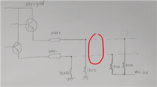
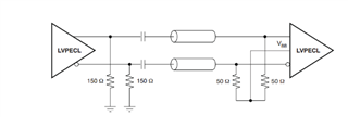
Now I want to use the chip to design the circuit of LVPECL output AC configuration,

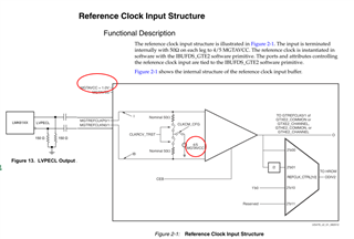
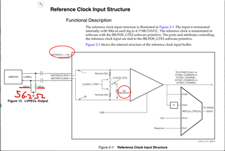
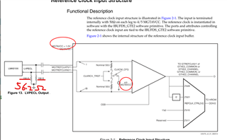
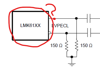
The application circuit diagram of the following figure is recorded in the data sheet。

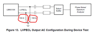
Question 1:How is the resistance of 150 Ohms calculated?

Question 2:What is the internal structure of the device output?

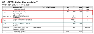
Question 3:Please also inform the relevant current parameters at the output end of the equipment

  • Hi Iongchang,

    Please allow me time to consolidate my response after I look through our files. I will get back to you by February 1st.

    Regards,

    Juan

  • Hi Juan,

    What's the result of the investigation

  • Hi Iongchang,

    Q1: The resistance of 150 Ohms is calculated to achieve a specific current value of roughly 30 mA to 40 mA. The typical termination on output drivers is 50 Ohms to a certain voltage, typically Vcc - 2 Volts. In this particular case, we are tying the output driver to ground. To achieve a current close to the aforementioned range, we need to use a 150 Ohm resistor. This can be calculated with Ohm's law, which gives us a current of roughly 33 mA.

    Q2: 

    You can find this image in the following collateral Interfacing Between LVPECL, VML, CML and LVDS Levels

    This document may be of use to you beyond the image based on the questions you asked.

    Q3: Answered in Q1.

    Regards,

    Juan

  • Hi Juan,

    Q1: 

    “pecific current value of roughly 30 mA to 40 mA”Is it the current of the internal current driver?

    Is the current(33mA) calculated according to the circuit diagram below?

    How is the 33 mA current calculated?

    new Q2:

    The following diagram is the circuit diagram to be designed,Terminal voltage is 0.8V(1*4/5)、

    What is the appropriate value to change the resistance of 150 Ohms?

  • Hi Ionchang, I will contact the designer to verify your two questions. Apologies for the delay.

  • Hi Juan,

    When can  reply?

  • Hi Iongchang,

    Q1: Make sure you AC couple the signal in between the 150 Ohm resistors and the 50 Ohm resistors.

    Q2: You do not need to change the 150 Ohm resistance. The design in that reference clock input structure is correct as is.

    Regards,

    Juan

  • Hi Juan,

    1.How is the 33 mA current calculated?

    2.

    If the resistance value of 150 ohms is changed to 56.2 ohms,the resistance of the terminal does not change,

    From the perspective of AC coupling,      I=800mv/(56.2//50)=30.2mA,Is the calculation formula correct?

  • Iongchang, let me clarify.

    1. The ~roughly 30 mA current is total from the positive and negative channels. I apologize for the confusion. At the positive node, we will have an ideal voltage of  Vcc - Vbe = 2.5V. To get current we do 2.5 V/150 Ohms = 16.67 mA. The negative channel node will be at at 1.7V (3.3V - 0.8V- 0.8V). 1.7 V/150 Ohms = 11.33 mA.

    2. That calculation formula is not correct. 

  • Hi Juan

    1.In order to ensure the normal output signal of the chip, is there any requirement for the size of the current value flowing from the positive and negative channels?  Or say In order to ensure the quality of the output signal, what is the most appropriate adjustment of the current value from the positive and negative channels?

    2.If the resistance value of 150 ohms is changed to 56.2(As shown in the circuit diagram)

    According to the parameters in the data sheet At the positive node,

    we will have an voltage of Vos + Vod/2 = 3.3-1.55+0.4=2.15V.The negative channel node will be at at 1.35V (3.3V - 1.55V- 0.4V).

    at R=150ohms To get current we do (I+)=2.15/150=14.33mA,(I-)=1.35/150=9mA,I=(I+)+(I-)=23.33mA

    at R=56.2ohms To get current we do (I+)=2.15 V/56.2 Ohms = 38.26 mA,,(I-)=1.35 V/56.2 Ohms = 24.02 mA, I=(I+)+(I-)=62.28mA

    The current value of R=150 ohms is smaller than that of R=56.2 ohms, so R=150 ohms is more appropriate?


  • Hi Iongchang,

    1. I believe this should help. Two 150-ohm resistors are used for DC biasing the LVPECL output emitter follower, and the values are calculated based on setting the output transistor emitter current at the switching threshold.  Because the output biasing resistor is placed at the driver side before the coupling capacitors, the line termination resistors and input biasing must be provided at the receiver side.  Typically, we want our LVPECL output currents to each be ~15 mA. 

    LVPECL DC Termination Current Calculation
    Temp VCC (V) VT=VCC-2V (V) VBE (V) RE (ohm) VP=VCC-VBE (V) IP=(VP-VT)/RE (A) VN=VCC-VBE-0.8 (V) IN=(VN-VT)/RE (A) IT_Per_Output (A) Comments
    -55 3.3 0 0.9 150 2.4 0.016 1.6 0.010666667 0.026666667 Note VT Changes to 0V for customer use case.
    25 3.3 0 0.8 150 2.5 0.016666667 1.7 0.011333333 0.028  
    125 3.3 0 0.7 150 2.6 0.017333333 1.8 0.012 0.029333333  


    2. 150 Ohms is more appropriate. 

    I hope this helps!

    Regards,

    Juan