This thread has been locked.

If you have a related question, please click the "Ask a related question" button in the top right corner. The newly created question will be automatically linked to this question.

LMK03318: Uncertainity in clock output

Part Number: LMK03318

Hi, 

Below is my applicaiton schematic for LMK03318, the device is programmed for the LVPECL output of 500MHz

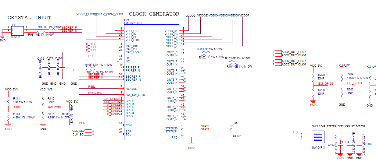
I am using register programming straight away to see the clock output

I have a found a minor glitch, i am not sure why its occuring

below are my output waveforms, output swing through a diff probe is below for a programmed 500MHz clock output

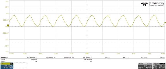
but when i increase timescale, i see the clock source is stagnant for 1ms for every 100ms, why this might be happening ? below is waveform

i did below experiment

Step 1: clock is out after programming

Step 2 : OFF all DIP switches

Step 3 : I can observe the Clock being similar

Step 4 : i have a again Enabled 3300pF to LF1 which made the clock to be stable with out any restart every 100ms

I could not understand why this process made the clock stable , why should i play with the LF1 cap at run time ?

i am also attaching the configuration file

  • Shyam,

    This is unusual - I will try loading this configuration file onto an EVM and see if I can replicate the issue. I will have a response for you by tomorrow.

    Thanks,

    Kadeem

  • Shyam,

    I loaded your configuration onto an EVM and did not see this issue occur.

    When you start up, do you start up with all three switches in the off position? The C2 capacitor is required for stability - if you are not using one of these three capacitors at startup, that would explain why you are seeing this issue.

    If you start up with the 3.3nF capacitor, do you still see the issue?

    Thanks,

    Kadeem

  • yes c2 is always present, its not distrubed

    i am not exactly clear why the clock goes unstable for every 100ms for a span of 1ms, why is this occuring ?

  • Shyam,

    I am not sure - it is not something that I have been able to replicate in the lab with our EVM.

    I am wanting to ensure that I understand your process properly - you said that with "off all DIP switches" you observe a similar result to what you had above. Do you mean that you start with the C2 capacitor connected, and only when you toggle does the issue go away? 

    Does this issue still occur if a different capacitor in the bank is selected at startup? 

    Does this issue still occur if your loop filter type is changed from third order to second order?


    Thanks,

    Kadeem

  • I will try above what ever you have said

    one clarity i need is, as i am programming registers via I2C and i am not flashing the EEPROM, is it happening because of that  ?

    what does the EVK do ?  the clock tool programs the EVKs EEPROM or permanant memory ? 

  • Hi,

    I have tried all ways only works is program and then change the switch state back and forth that means off the 3.3nF and on it again, this works fine to give a proper clock output, i am not sure if it cross linked to any other problem, can you mail me at my mail id or provide yours, i shall post you my schematic and layout, is there any thing wrong in layout which is causing this ?

  • Shyam,

    To answer your first question, when using the EVM with TICS Pro, writing all of the registers by default only writes to the active registers, not the EEPROM. However, what I did when performing the test is write the configuration that you sent to EEPROM, then test after a power cycle, without seeing the issue before and after the power cycle.

    If you can email both to k-samuel@ti.com, I can review the documents.

    I am in the lab again today to investigate this issue, and will let you know if I observe anything different.

    Thanks,

    Kadeem

  • Shyam,

    I have a couple of questions for you:

    1. Is this issue on just a single board, or do you have multiple boards all exhibiting this behavior?

    2. Have you probed the oscillation of the XTAL directly? Is this behavior present directly from the XTAL?

            a. What you can do is set the output of Status0 to PLL RDIV/2 on the status page, and then probe the Status0 pin.

    I will run the loop filter settings through PLLatinum Sim, and see if there are any issues.

    Thanks,

    Kadeem