Other Parts Discussed in Thread: SE555, TLC555
Hi
I need to know max freq of operation of the SE555-SP part and if there is a PSPICE model available?
Thanks
This thread has been locked.
If you have a related question, please click the "Ask a related question" button in the top right corner. The newly created question will be automatically linked to this question.
Hello Ron,
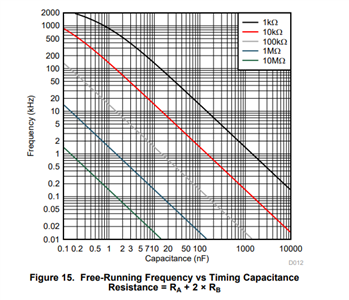
For the SE555 we show up to 100 kHz of linear operation in the free running frequency plot of Figure 14. Although the device may go beyond 100 kHz, there is not enough information regarding propagation delays to provide guidance on how to achieve a target frequency beyond 100 kHz. The TLC555 does provide information beyond 100 kHz and the proper equations to calculate your designs target frequency at higher frequencies. If you need to operate beyond 100 kHz, I recommend looking at the TLC555. You will need to account for propagation delays and board parasitic capacitance in order to achieve your design goals at high frequencies using these devices. The TLC555 has the best spice model. Inside of Tina there is an SE555 generic model under the generic 555 IC. If you double click the 555 device in Tina, it can be changed to the SE555.
Best Regards,
Chris Featherstone
Hi Ron,
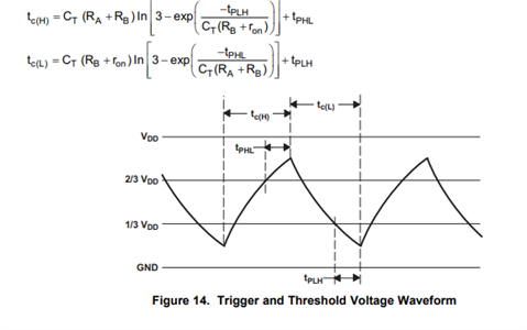
The propagation delays of the 555 timer itself would need to be considered at frequencies above 100 kHz. For example, in the TLC555 product datasheet there are two sets of equations. The most simple set of equations applies to frequencies under 100 kHz. For frequencies beyond 100 kHz, the equations below apply. In the waveform below you will see the TPHL and TPLH parameters. These are the propagation delays. They need to be measured in a given application circuit. In addition the board parasitic capacitance should be measured at the node that the timing capacitor is attached to. The parasitic cap value should be lumped into the parameter CT below. This is the timing cap plus the parasitic value combined. Accounting for the board parasitic capacitance will help better align the design frequency with the actual performance.

There are some general best practice guidelines to follow for minimizing parasitic capacitance in the layout of the PCB.
Looking at the free running frequency curve for the TLC555 you can see red and black curves are non-linear at higher frequencies. This is due to the propagation delays. For the timing capacitor, a COG/NPO type is recommended. The larger the timing cap is relative to board parasitic capacitance the better.
Best Regards,
Chris Featherstone
Hi Ron,
I forgot to attach the free running frequency curve I referenced in my last post.

Best Regards,
Chris Featherstone
Hello Ron,
No problem. Let me know if you have further questions. Here are some additional resources that you may find useful:
Best Regards,
Chris Featherstone