This thread has been locked.

If you have a related question, please click the "Ask a related question" button in the top right corner. The newly created question will be automatically linked to this question.

LMK04828: Status LED is not bright

Part Number: LMK04828
Other Parts Discussed in Thread: ADC34J25

Dear TI support,

I got one problem on LMK04828.

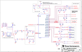
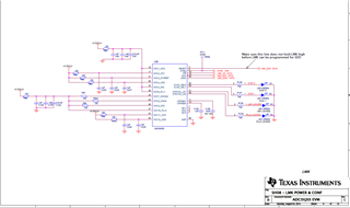
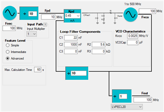
I copied the schematic from the ADC34J25. Please see below.

But when I finished the configuration, we can make sure the PLL1 and PLL2 are both locked according the LEDs status.

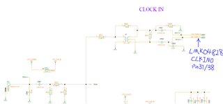
I use 10MHz input for PLL1 reference, which is coming from keysight network analyzer 10M out.

Please see belwo pic, the PLL1 status LED H22 is not so bright as the H23. 

Could you please support this problem? Does it mean PLL1 and PLL2 are all locked now? Why H22 is so weak?

Thanks for your time

Best Regards,

Brooke

  • Hello Brooke,

    Could you link that schematic?

    Also, for me to make sure if the PLLs are locked, I would need your TICS Pro file, loop filter design, and frequency plan to double check, could you please attach those? That light does seem very low and I would assume it could be cause an unlocked PLL. Thanks!

    Best,

    Andrea

  • Hello Andrea,

    Thanks for your quick response.

    I copied the schematic from the following set-up.

    Please see our project schematic as below. Here we want to use CLKIN0 for PLL1 reference at the moment.

    Loop filter and VCXO:

    PLL1 input reference


    Attached the CFG file below.

    LMK04828.cfg

    Frequency plan:

    PLL1:

    Reference: 10M; PDF: 10MHz. VCXO = 100M

    PLL2

    Reference: 100M; PDF: 100MHz. VCXO = 2400M

    Any additional information need to be known, please let me know.

    Best Regards,

    Brooke

  • Hello Brooke,

    To make sure the LED is not the problem, could you check it if the voltage fed into the lit up LED is different than the off LED? If that's the case, please attach your .tcs file since there is a problem with the PLL locking. If not, then your device is locking and it's just a faulty LED.

    Thanks,

    Andrea

  • Hello Andrea,

    I have no .tcs file here. Because I only use ADC34J25 evaluation board for register value generation.

    Please see below settings for the register. Based on our schematic above, could you please share with us your suggestions? 

    Thanks for your time.

    LMK04828
    0x00 0x00
    0x02 0x00
    0x100 0x68
    0x101 0x55
    0x103 0x01
    0x104 0x22
    0x105 0x00
    0x106 0xF0
    0x107 0x11
    0x108 0x78
    0x109 0x55
    0x10B 0x01
    0x10C 0x22
    0x10D 0x00
    0x10E 0xF1
    0x10F 0x01
    0x110 0x68
    0x111 0x55
    0x113 0x01
    0x114 0x02
    0x115 0x00
    0x116 0xF0
    0x117 0x10
    0x118 0x78
    0x119 0x55
    0x11B 0x01
    0x11C 0x22
    0x11D 0x00
    0x11E 0xF1
    0x11F 0x01
    0x120 0x70
    0x121 0x55
    0x123 0x01
    0x124 0x22
    0x125 0x00
    0x126 0xF0
    0x127 0x11
    0x128 0x70
    0x129 0x55
    0x12B 0x01
    0x12C 0x22
    0x12D 0x00
    0x12E 0xF0
    0x12F 0x16
    0x130 0x62
    0x131 0x55
    0x133 0x01
    0x134 0x02
    0x135 0x00
    0x136 0xF0
    0x137 0x16
    0x138 0x10
    0x139 0x03
    0x13A 0x00
    0x13B 0xF0
    0x13C 0x00
    0x13D 0x08
    0x13E 0x03
    0x13F 0x00
    0x140 0x00
    0x141 0x00
    0x142 0x00
    0x143 0x12
    0x144 0xFF
    0x145 0x7F
    0x146 0x1F
    0x147 0x4A
    0x148 0x13
    0x149 0x53
    0x14A 0x02
    0x14B 0x16
    0x14C 0x00
    0x14D 0x00
    0x14E 0x00
    0x14F 0x7F
    0x150 0x03
    0x151 0x02
    0x152 0x00
    0x153 0x00
    0x154 0x01
    0x155 0x00
    0x156 0x01
    0x157 0x00
    0x158 0x96
    0x159 0x00
    0x15A 0x0A
    0x15B 0xC0
    0x15C 0x20
    0x15D 0x00
    0x15E 0x00
    0x15F 0x0B
    0x160 0x00
    0x161 0x01
    0x162 0x44
    0x163 0x00
    0x164 0x00
    0x165 0x0C
    0x166 0x00
    0x167 0x00
    0x168 0x0C
    0x169 0x41
    0x16A 0x20
    0x16B 0x00
    0x16C 0x00
    0x16D 0x00
    0x16E 0x13
    0x17C 0x15
    0x17D 0x33

    Best Regards,

    Brooke

  • Hello Brooke,

    Going back to my previous post, did you test the voltages of the LEDs? If so, what were their values?

    Best,

    Andrea

  • Hi Andrea

    I have checked the LED indictors of LNK04828. PIN32 voltage is 0V, and PIN 48 is 3.3V.

    Would you think the population of R818 has influence for the PLL1 locking?

    Best Regards,

    Brooke

  • Hello Brooke,

    Yes, that resistor could be causing your PLL1 to not lock. If you notice the topology you have for your second loop filter (coming out of CPout2), you don't have a resistor connected to VCC. I'm not entirely sure why they do that on the ADC34J25EVM board, but that resistor should not be needed.

    What I believe is happening is that your loop filter is unstable, and an unstable loop filter cannot provide a reliable signal back into the LMK04828 to lock the PLL. Therefore, I recommend to change your PLL1 loop filter to look as the picture below (note that this is assuming your charge pump current is 450 uA, the hex file you sent over did not properly translate):

    Hope this helps!

    Best,

    Andrea

  • Hi Andrea

    I removed the resistor R818 and changed the register address 0x15B value from 0xC0 to 0xD4.

    I use the positive slope for the VCXO which PN: CVHD-950-100M. And then PIN 32 voltage is around 3.3V. The LED is on.

    Here I didn't use your recommended loop filter above. Maybe later I need to optimize it according to our requirement.

    Could you please let me know the root cause for my unlocked PLL1 previously? With many thanks.

    Best Regards,

    Brooke

  • Hello Brooke,

    To ensure lock, you have to select the correct polarity for the slope of your VCXO. Your VCXO has a positive slope as established on the VCXO's data sheet. How the PLL works is that is sends current pulses to the VCXO letting it know to either speed up or slow down. This change in speed (or frequency) is what's changed to achieve lock for the PLL. With the wrong VCXO slope polarity, those commands are flipped (i.e, the PLL is telling the VCXO to slow down when it should speed up), meaning the phases will not be equal (the inputs to the phase detector/charge pump block below) and the PLL will never lock.

    Best,

    Andrea

    Andrea

  • Hi Andrea,

    Thanks for your detailed description. I think we have resolved this issue.

    Thanks again for your time.

    Best Regards,

    Brooke