This thread has been locked.

If you have a related question, please click the "Ask a related question" button in the top right corner. The newly created question will be automatically linked to this question.

LMK61E07: What are the functions of the SWR2PLL, AUTOSTART and ENCAL register bits?

Part Number: LMK61E07
Other Parts Discussed in Thread: LMK61E2,

Hi team,

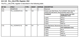
What is the function of these register bits (SWR2PLL, AUTOSTART and ENCAL)? How to use them?

Does both the AUTOSTART bit and the ENCAL bit have a function to trigger PLL Lock?

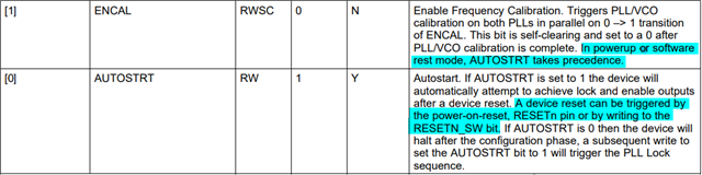
For ENCAL bit, what is software rest mode?

Device does not have RESETn pin and RESETN_SW bit, how do user use the AUTOSTRT bit?

Could you lease leave your comments? Thanks in advance.

Best Regards,

Amy Luo

  • The customer's specific doubts are:

    With AUTOSTART set to 1,

    1. Modifying the output frequency 125MHZ->100MHZ: Write PLL register configuration with OUTDIV -> set SWR2PLL=1 -> Lock

    2. Modifying the output frequency 100MHZ-> 125MHZ: Write PLL register configuration with OUTDIV ->set  SWR2PLL=1 -> Output frequency is not correct and PLL Loss of Lock -> Set SWR2PLL=1 again -> Lock 

    3. Modifying the output frequency 100MHZ-> 125MHZ: Write PLL register configuration with OUTDIV -> set SWR2PLL=1 -> Output frequency is not correct and PLL Loss of Lock  -> set ENCAL=1 -> Output frequency is not changed and PLL Loss of Lock.

    Why do the 1 and 2 outputs above have different LOCK states?

    When AUTOSTART is set to 0,

    1. Modifying the output frequency 125M->100M: Write PLL and OUTDIV -> SWR2PLL=1 -> output without clock -> AUTOSTART=1 or ENCAL=1 -> Lock

    2. Modifying the output frequency 100M-> 125M: Write PLL and OUTDIV -> SWR2PLL=1 -> output without clock -> AUTOSTART or ENCAL=1 -> Lock

  • Hi Amy,

    I see that there are some strange statements in the datasheet (e.g. nonexistent RESETn pin and mention of two PLLs even though this device only has one). It is possible that the register R10 (DEV_CTL) that contains the ENCAL and AUTOSTRT bits is deprecated and not recommended for customer use. I also do not currently have a method of accessing ENCAL and AUTOSTRT with my engineering tools, so for now I can't test issues related to them in the lab.

    The SWR2PLL bit resets the VCO calibration and clock dividers and I think it is supposed to be written after making changes to the PLL settings, but I do not know the specifics yet.

    I tested the issue with 100 MHz <----> 125 MHz and SWR2PLL in the lab with an EVM containing the LMK61E2 (slightly different device but uses the same register map). I was not able to replicate the "Modifying the output frequency 100MHZ-> 125MHZ: Write PLL register configuration with OUTDIV ->set  SWR2PLL=1 -> Output frequency is not correct and PLL Loss of Lock -> Set SWR2PLL=1 again -> Lock " behavior. I noticed that the output frequency changed the moment I wrote to the output divider registers and triggering SWR2PLL afterwards would not break the lock or make a persistent incorrect output frequency. I did notice that there would rarely be an incorrect output frequency for a very brief time after triggering SWR2PLL, but it would immediately correct itself.

    I am checking with my team to verify the status of register R10 and see if they have more ideas for the bolded issue I was not able to replicate. Does the customer know how often that problem happens?

    Thanks,

    Evan Su

  • Hi Evan,

    Much appreciated.

    Here's what I've received from the customer:

    This phenomenon occurs at 100% frequency with a specific configuration, and I tested it on 4 chips, and it was all the same. I modified the frequency not only OUTDIV but also PLL-related configuration, using the following configuration: Unmarked registers use the Reset value in the Datasheet. I can provide the Linux sheel script that I configure to use if need it.

    100MHZ

    ADDR 21 23 26
    VAL 0x03 0x2e 0x2e

    125MHZ

    ADDR 21 23 26
    VAL 0x03 0x28 0x32

    Best Regards,

    Amy

  • Hi Amy,

    I have learned that register R10 was inherited from an older product and there typically should not be a reason for customers to program it. The device's EEPROM by default has AUTOSTRT = 1, so the device will automatically calibrate its VCO after power-on and after manually triggering a software reset through the SWR2PLL bit, which is generally desired behavior. ENCAL manually triggers the VCO calibration but I think it makes more sense to use SWR2PLL instead, which exists in the fully supported register R72.

    I ran some tests in the lab today using in the information you provided. First I configured my device to correctly output a 100 MHz HCSL signal using a N-divider of 0x2e (therefore VCO frequency of 4600 MHz) and output divider of 0x2e. I wrote 0x28 to R23 to change the output divider, the output signal became 4600 MHz / 40 = 115 MHz as expected. Then I wrote 0x32 to R26 to change the N-divider to decimal 50, the output signal deviated to around 116.42 MHz as expected (PLL has not been allowed to recalibrate yet). Finally I wrote 0x02 to R72 to trigger the SWR2PLL software reset and the correct output frequency of 125 MHz immediately appeared. So I was again unable to replicate the problem because I achieved a stable 125 MHz output after the first SWR2PLL reset.

    I think it would help to have the customer's configuration code, I would like to check the initial register configuration and the subsequent writes for next week.

    Thanks,

    Evan Su

  • Hi Evan

    I am the customer that Amy mentioned.I have this problem with both the Linux shell and the U-boot driver。

    That is the Linux shell script I use.You can save it as a .sh file and use it.

    It uses i2c port 0 by default, you can configure the i2c_index environment variable to change it.

    Here are parameters :

    -f $value(100 or 125) : change frequency to 100 or 125 MHz.

    -r : Set register to reset value.

    -s : Save register to EEPROM.

    #!/bin/bash
    
    i2c_index=${I2C_INDEX:="0"}
    dcxo_addr=${DCXO_ADDR:="0x59"}
    
    outdiv_by0_100m='0x2e'
    pll_n_by0_100m='0x2e'
    pll_lf_r2_100m='0x04'
    
    outdiv_by0_125m='0x28'
    pll_n_by0_125m='0x32'
    pll_lf_r2_125m='0x08'
    
    # Reset to default value
    reset() {
        i2ctransfer -y $i2c_index w2@$dcxo_addr 10 0x01
        i2ctransfer -y $i2c_index w3@$dcxo_addr 16 0x00 0x00
        i2ctransfer -y $i2c_index w20@$dcxo_addr 21 0x01 0x00 0x20 0x00 0x00 0x64 0x00 0x00 0x00 0x00 0x00 0x00 0x0c 0x24 0x03 0x08 0x00 0x00 0x00
        i2ctransfer -y $i2c_index w2@$dcxo_addr 42 0x00
        i2ctransfer -y $i2c_index w2@$dcxo_addr 49 0x10
    }
    
    
    # Set output clock
    set() {
        i2ctransfer -y $i2c_index w2@$dcxo_addr 21 0x03
        i2ctransfer -y $i2c_index w2@$dcxo_addr 23 $1
        i2ctransfer -y $i2c_index w2@$dcxo_addr 26 $2
        i2ctransfer -y $i2c_index w2@$dcxo_addr 36 $3
        i2ctransfer -y $i2c_index w2@$dcxo_addr 72 0x02
    }
    
    
    # Save to EEPROM
    save() {
        i2ctransfer -y $i2c_index w2@$dcxo_addr 49 0x50
    
        sleep 0.2s
    
        i2ctransfer -y $i2c_index w2@$dcxo_addr 56 0xbe
        i2ctransfer -y $i2c_index w2@$dcxo_addr 49 0x12
    
        sleep 0.2s
    
        i2ctransfer -y $i2c_index w2@$dcxo_addr 56 0xbe
        i2ctransfer -y $i2c_index w2@$dcxo_addr 49 0x11
    
        sleep 0.2s
    
        i2ctransfer -y $i2c_index w2@$dcxo_addr 56 0x00
    }
    
    while getopts :f:sr argv ; do
        case $argv in 
        f)
            if [ $OPTARG -eq 100 ] ; then
                set $outdiv_by0_100m $pll_n_by0_100m $pll_lf_r2_100m
            elif [ $OPTARG -eq 125 ] ; then
                set $outdiv_by0_125m $pll_n_by0_125m $pll_lf_r2_125m
            else
                echo "Invalid freqency"
    
            fi;;
        s) save;;
        r) reset;;
        [?]) echo "invalid option or miss option argument";;
        esac
    done

    Best Regards,

    Blue Zhang

  • Hi Blue,

    Our response will be delayed due to the US holiday on February 20, 2023. We will get back on the following day.

    Best,

    Asim

  • Hi Blue,

    I am back from the holiday. Thank you for providing the code, I am looking it over and will let you know soon if I see anything unusual.

    By the way, it is possible to switch between 100 MHz <----> 125 MHz by changing only the output divider value (register R23). For example, if we configure the VCO to run at 5000 MHz only (register R26 = 0x32), an output divider value of decimal 50 leads to 100 MHz output and decimal 40 leads to 125 MHz output. This is what I did on Feb 16 and avoids changing the VCO frequency, so a software reset to recalibrate the VCO should not be required. The only potential downside is that the phase noise performance for the 125 MHz output at VCO frequency = 5000 MHz may be slightly different from at VCO frequency = 4600 MHz, but it may be fine for your application. I am still investigating the loss of lock behavior because it is strange and unexpected, but this is a possible workaround.

    Thanks,

    Evan Su

  • Hi Evan,

    Thank you for your reply.

    I have recommended this solution to Blue, but he wants to know why this anomaly is occurring to avoid possible problems in future use. 

    Regards,

    Amy

  • Hi Evan,

    Thank you for your reply.

    I wrote the U-boot driver to configure the LMK61E07, through which the user may tune the LMK61E07 to any frequency that is feasible, so I need to avoid this uncertainty.

    By the way, the chip REVID is 0x03.

    Best Regards,

    Blue Zhang

  • Hi Blue,

    I checked the set() function and it looks like the loop filter R2 value (in register R36) is being altered when switching between 100 and 125 MHz, which I was not aware of before. This should be OK but I will try it in the lab tomorrow to see if it is related to the loss of lock.

    Thanks,

    Evan Su

  • Hi Evan,

    This still happens when I don't change the R36 value.

    Best Regards,

    Blue Zhang

  • Hi Blue,

    I studied the code for the reset() function and noticed one line of code that was unusual. It looks like it is writing 0x00 to register R42. R42 contains two settings for VCO calibration.

    R42 is hidden from my internal GUI so I assume that we do not intend for customers to modify it. Writing it to 0x00 will set the analog closed loop stabilization time and the VCO wait time to their minimum values, which is not recommended and may not give the VCO enough time to properly recalibrate after you initiate a software reset. This could be the cause of your observed issue if you ran reset() at any point before changing output frequencies or if this register value has been written to EEPROM.

    I believe the recommended/default value for R42 based on the datasheet description should be 0b00001001 = 0x09. Try writing that to R42 and let us know if it fixes the loss of lock issue. If it does, ensure that R42 has the correct value of 0x09 in EEPROM and avoid editing it in the future.

    Thanks,

    Evan Su

  • Hi Evan,

    Thank you for your support.

    I tested and changed the R42 value and it solved the problem.

    However, I found that in the Datasheet, Reg map and Reg description have different reset values, and both values do not output the default frequency of 70.656MHz, and the Reg map value even exceeds the upper limit of PLL output frequency.

    Here are the differences I found

    | Reg                       | 17   | 26   | 34   | 36   | 42   |
    | ------------------------- | ---- | ---- | ---- | ---- | ---- |
    | Reg map reset val         | 0x00 | 0x64 | 0x24 | 0x28 | 0x00 |
    | Reg description reset val | 0x80 | 0x32 | 0x28 | 0x08 | 0x09 |

    Best Regards,

    Blue Zhang

  • Hi Blue,

    Happy to hear that the loss of lock problem has been resolved. Thank you for pointing out the contradictions in the datasheet, I'll work on getting them reviewed and revised. I may need to investigate the factory programmed configuration of the device. If you are interested, I can also generate a custom register map for you to reset the device to a known good state using your script.

    Best,

    Evan Su