This thread has been locked.

If you have a related question, please click the "Ask a related question" button in the top right corner. The newly created question will be automatically linked to this question.

LMK00304: Propagation delay and part-to-part skew

Part Number: LMK00304

Hi experts,

I'm using LMK00304 in my design. there are two parts in my board, both inputs are driven by two outputs of a PLL with the same frequency and same phase, the frequency is 100MHz, I want to calculate the propagation delay and skew. I'm confused with the parameters in datasheet.

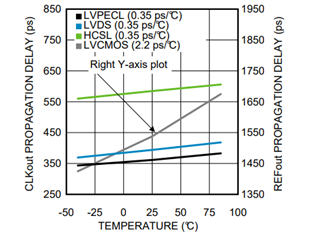
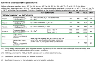
For propagation delay, it's 200ps - 400ps - 600ps, min-typical-max.

While the Part-to-part output skew is 80ps -120ps, typical-max.

if I had one component with a propagation delay of 200ps, and the other was 600ps, then the Part-to-Part skew must be like 600ps -200ps = 400ps, then how do you get the Part-to-part skew of 80ps-120ps, which should be impossible.

Any suggestion? 

Regards

Chris

  • Hi Chris,

    The two statistics are measured and tested differently. The propagation delay statistics of 200 ps min, 400 ps typ, 600 ps max are obtained by running an individual device at a wide range of operating conditions. The part-to-part skew statistics of 80 ps typ and 120 ps max are obtained by taking multiple devices from the same production lot and testing them in the same operating conditions; the part-to-part skew test is supposed to measure the intrinsic device differences within a batch and the other variables are controlled as best as possible.

    The 200 ps minimum delay and 600 ps maximum delay were most likely measured under very different operating conditions, maybe at the minimum and maximum operating temperatures for example. So when we compare two devices in a part-to-part skew test in the same conditions, it is very unlikely that one device will have 200 ps delay and the other one will have 600 ps delay at the same time. The delays should instead be quite similar and that explains why the part-to-part skew is less than the range of possible propagation delays. This should be a fair representation of most customer systems because we typically would not expect extreme temperature differences between one device and another.

    Thanks,

    Evan Su

  • Hi Evan,

    Thanks for your quick response. I understood the definition of part-to-part skew.

    In my system, the propagation is also a key parameter, there is no info about the relationship between temperature range, voltage, etc with the propagation delay. If I evaluate the system performance with the minimum (200ps) and maximum(600ps), the variation will be huge for my devices.

    1) Do you have any data to show the influence of temperature, voltage or others on the propagation delay?

    2) For my case, the temperature range is like 10-70 degree Celcius, no vibration, it's kind of a lab environment, should I use the typical? Or I have to do some measurement before I can make a decision, what if the batches of LMK00304 are different, I can't run test every time.

    Regards

    Chris

  • Hi Chris,

    Figure 17 in the LMK00304 datasheet shows a plot of propagation delay vs temperature:

    You can use this curve to look up expected propagation delay for a given temperature. At room temperature the delay is about 400 ps, so it's similar to the typical value. The typical part-to-part skew of 80 ps should be a decent estimate of the variation in propagation delay between devices. I am not very familiar with this part so I don't have more specific advice or additional data on hand, but I can check with my team tomorrow if you have more questions.

    Thanks,

    Evan Su

  • Hi Evan,

    Thank you very much, I didn't notice that there is a curve about the propagation delay vs temperature. I can use it to move forward.

    My last question is about the voltage, e.g., the VCC core or VCCO power supply, will it have impact on propagation delay, or the influence is negligible?

    Regards

    Chris

  • Hi Chris,

    The core and output supply voltages may have some effect on the propagation delay. However I do not have any information on the specifics, all the propagation delay/skew information presented in the datasheet is for V_CC = 3.3 V, V_CCO = 3.3 V. If you are interested, I can ask our validation team to see if they have any relevant data.

    Thanks,

    Evan Su

  • Thanks, it will be great if I can get some info about the influence caused by VCC/VCCO. Actually I have several different TI buffers in my design, it's good to learn more info.

    Regards

    Chris

  • Hi Chris, I will check with the validation team then and let you know when I hear back. 

  • Thank you.

  • Hi Chris,

    I looked through the validation data for this device and was not able to find any information on the propagation delay. This is an old device that was developed before our current organization system was introduced and it is possible that the files were misplaced. Best of luck on your design, feel free to contact us if you have any more questions in the future.

    Thanks,

    Evan Su