Other Parts Discussed in Thread: CDCEL913, CLOCKPRO, CDCE925
Hello, can you provide the driver demo of cdcel913?
This thread has been locked.
If you have a related question, please click the "Ask a related question" button in the top right corner. The newly created question will be automatically linked to this question.
Hi Huizhou,
What driver you are referring to?
Can below application note help you?
Hi Huizhou,
Please download ClockPro to help you on register configuration.
Ds90ub941as q1 is a deserializer. I use 913 as the reference clock for 941 here. I only need to configure the value of the 0x56 register as 0x01. Do I need to configure any other registers.I am using the splitter mode. When 913 outputs 184mhz to 941, one screen has vertical stripes and the other screen is black.
HI Noel Fung,
I have encountered a new problem.My input frequency is 27 mhz.I want Y1 to output 192mhz and Y2 to output 184mhz.
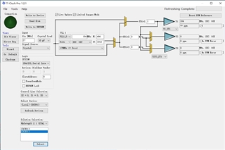
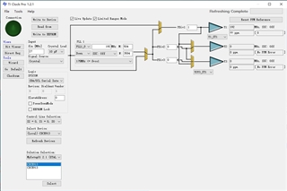
1.This is my configuration.I have configured two outputs.

2.But the result I got was two Y1 outputs.What is the function of this select button.
How can I configure to obtain two outputs Y1 and Y2 at once.


Thank you for your support
Regards,
Huizhou
HI Noel Fung,
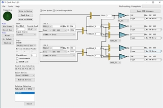
The following figure shows the output I obtained after using cdce925.
But we have already used the machine of cdcel913 and it is already in production.
Do we have to switch to cdce925 in this case? Does it mean that cdcel913 cannot meet our requirements for both Y1 and Y2 outputs?

Thank you for your support
Regards,
Huizhou
HI Noel Fung,
When I use the 192mhz clock frequency divided by 8155, the screen can display stably.
When using the 192mhz clock frequency given by cdcel913, it was found that there was a slight jitter in the frequency and a jagged pattern around the image.
From the oscilloscope, it can be seen that the frequency of the REFCLK pin of 941 is also unstable.
Thank you for your support
Regards,
Huizhou
Hi Noel,
I am the FAE who supports Pateo, we don’t have to worry about the related settings of FPDLINK, and now I want to help customers confirm whether CDCEL913 can be configured with Y1 to output 192mhz and Y2 to output 184mhz.
913 cannot generate two non-integer multiple clock frequencies simultaneously.
Is the integer multiple mentioned here 10 as an integer? Such as 180, 190, etc. Or the ones digit is an integer, and there is no decimal point.
Can I only switch to CDCE925 for the above requirements?
Thanks!
Hi Alan,
As we can see from the diagrams, 913 has only one pll/vco and a P-divider, it can output fvco and fvco/P frequencies. For example, if fvco = 184MHz, possible 913 output frequencies are 184MHz, 92MHz, ........
In order to get both 184MHz and 192MHz, we need two pll/vco.