Part Number: LMK05318B
Hi Team:
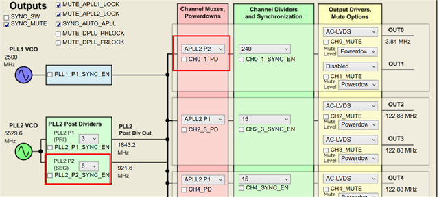
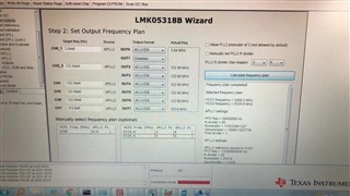
My customer use LMK05318B with 1.7.2.0 version to create some config file ,it show the frequency plan can work which OUT0/1=>3.84Mhz ,so customer base on this logic and finish the PCB ,but when they check the PCBA of OUT0, it become 7.68MHz.
So i check that the 1.7.2.0 version can pass the frequency plan but output a wrong frequency in the real PCBA.
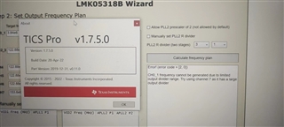
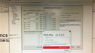
And the 1.7.5.0 & 1.7.5.7 version show below message:
Error! (error code = [2, 0])
CH0_1 frequency cannot be generated due to limited output divider range. Try using channel 7 as it has a large output divider
Could you help me take a look at this case to make this work following customer config file? Since different version cause different result, it is like a hidden trap,if it can not work ,the customer may need to redesign the PCBA ,which is quite hard for them. tks again!
Here attached the customer config file: