This thread has been locked.

If you have a related question, please click the "Ask a related question" button in the top right corner. The newly created question will be automatically linked to this question.

CDCM6208V2G: ELF parts choice help?

Part Number: CDCM6208V2G
Other Parts Discussed in Thread: CDCM6208,

Hi TI Support,

    I am having a problem with the CDCM6208V2.  Can you help me?  I am almost certain it has to do with the external loop filter on the chip.  I know this because of all the debugging and testing I've done, also, this device worked well for me on Version 1 of my board where I had a slightly different ELF.  I am seeing noise up at 7.5 GHz created and dumped all over the board, but as I get my ELF closer to that of V1, I saw this start to disappear and the chip not be noisy. 

Here are the values I am programming into the registers (getting about 780 ish kHz out of the fractional divider outputs)

reg_config_t cdcm6208_reg_def[21] = {
    {0x0000, 0x01B8, 0}, // 0 // 01B8
    {0x0001, 0x0000, 0}, // 1
    {0x0002, 0x0013, 0}, // 2
    {0x0003, 0x08FA, 0}, // 3
    {0x0004, 0x30E3, 0}, // 4
    {0x0005, 0x0001, 0}, // 5
    {0x0006, 0x0000, 0}, // 6
    {0x0007, 0x0001, 0}, // 7
    {0x0008, 0x0000, 0}, // 8
    {0x0009, 0x06D3, 0}, // 9 0x06D3 for LVCMOS / 603 for lvds // 3
    {0x000A, 0x0D40, 0}, // 10
    {0x000B, 0x1352, 0}, // 11
    {0x000C, 0x0619, 0}, // 12 HCSL // B
    {0x000D, 0x0D40, 0}, // 13
    {0x000E, 0x1439, 0}, // 14
    {0x000F, 0x06D3, 0}, // 15 LVCMOS // 3
    {0x0010, 0x0D40, 0}, // 16
    {0x0011, 0x1352, 0}, // 17
    {0x0012, 0x06D1, 0}, // 18 LVCMOS // 3
    {0x0013, 0x0D40, 0}, // 19
    {0x0014, 0x1352, 1}  // 20
};

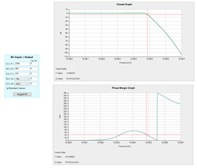
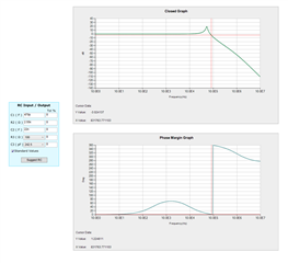
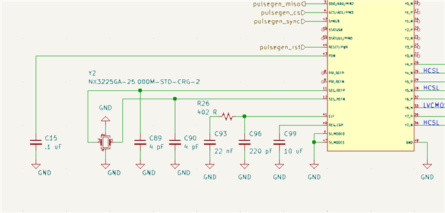
In the attached ELF and Clock.png picture, you can see the ELF values my circuit is using and the 25.0000MHz crystal I am using as my clock input.

V1, that worked had ELF values of 470 pF, 2.55k, and 22 nF.

Can you provide me with good ELF values given how I have this chip set up?  Do you know why V2 is having trouble and V1 isn't?  When I changed the values of V2 closer to that of V1 with what 0201 parts I had lying around, my sampling scope showed that the output would sometimes become not noisy, like something was on the verge of being stable.  Any ideas?

Thanks,
Matt

  • Hi Matt,

    I ran your V2 component values (both external and internal) through the Loop Filter tool in the CDCM6208V2G profile in TICS Pro and didn't see major problems. The only thing I noticed is that the phase margin at the -3 dB bandwidth is slightly below the guideline of 45 degrees.

    I checked the V1 configuration by setting C1 = 470 pF and R2 = 2.55k, keeping the result of the settings the same, and the resulting filter didn't look stable, it has a strange spike in the closed loop transfer function and did not have a stable phase margin at the -3 dB bandwidth.

    So based on this info it's unusual that V1 is performing better than V2, unless I am misinterpreting something? Did V1 have the same register configuration? I don't have any specific ideas at the moment but I recommend that you try out the Loop Filter tool yourself to check this apparent behavior as a starting point. There's also a Noise Transfer Graph function that might be helpful, although 7.5 GHz is an unusually high frequency and might be out of range.

    Thanks,

    Evan Su

  • Hi Evan, thank you for the quick reply.  I did a lot of debugging and trial and error parts changing on my end.  I also confirmed that the ELF wasn't the problem.  I did make my issue better by changing one thing.  I made a stupid mistake by shorting an LVCMOS pin to ground through a large capacitor (don't laugh).  I removed this and the features I was looking for in my analog circuitry started to appear, but the clock generator seems to be making a lot of noise still.  Is it possible that short circuiting the high frequency switching components to ground killed or messed up the LVCMOS the driver causing it to be noisy?

  • Also, I see the noise on all outputs of the clock generator.

  • Hi Matt,

    Happy to hear that at least the loop filter isn't involved.

    Is it possible that short circuiting the high frequency switching components to ground killed or messed up the LVCMOS the driver causing it to be noisy?

    If all the outputs are showing the noise, then the accidental grounding most likely wasn't the cause of the problem. I'd expect that the kind of disruption powerful enough to permanently affect the other drivers would leave that particular driver in a bad state.

    I'll check with my team to come up with more ideas. In the meantime I have a couple of questions to understand your situation better:

    • What region are you seeing the noise in the outputs, and can you tell me a bit about how you're measuring it? I've checked phase noise in clock gen outputs before in carrier offsets up to 40 MHz, and the 7.5 GHz noise you mentioned is unusual territory.
    • It sounds like the V1 version of the board did not have this problem. Did you program the device the same way on V1 and V2? If not, could you provide the configuration for V1 as well?

    Thanks,

    Evan Su