This thread has been locked.

If you have a related question, please click the "Ask a related question" button in the top right corner. The newly created question will be automatically linked to this question.

LMK5C33216EVM: 1-PPS input corresponding configuration register

Part Number: LMK5C33216EVM
Other Parts Discussed in Thread: LMK5C33216,

Hi team,

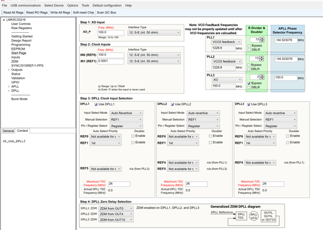
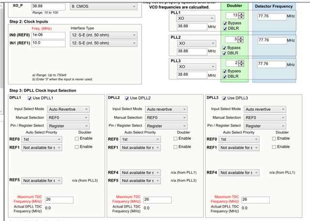
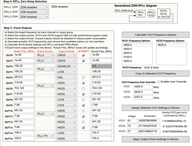
Could you help share the configuration register HexRegisterValues.txt for the 1-PPS input? The development board does not have a default configuration for 1-PPS and ZDM, which is less described in DS and is relatively difficult to use. The customer has tried 1-PPS input from REF0 as reference to DPLL2. DPLL2 ZDM from OUT0 (1 Hz clock signal from SYSREF). There are 3 main issues:

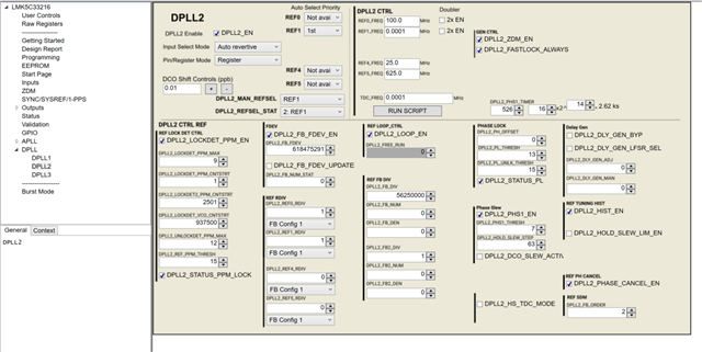
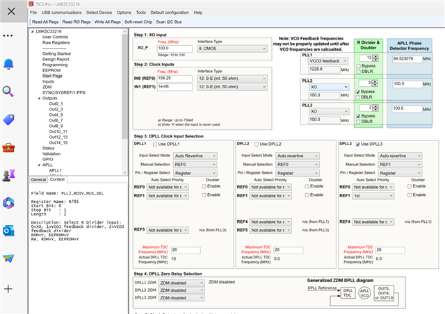
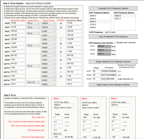
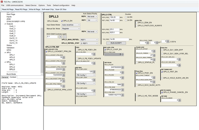
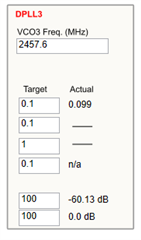
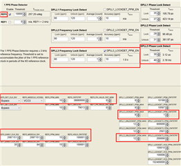
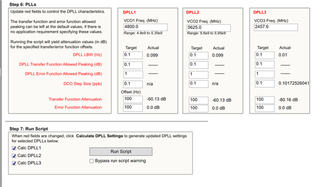
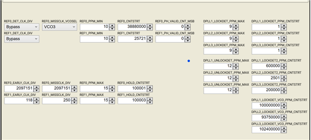
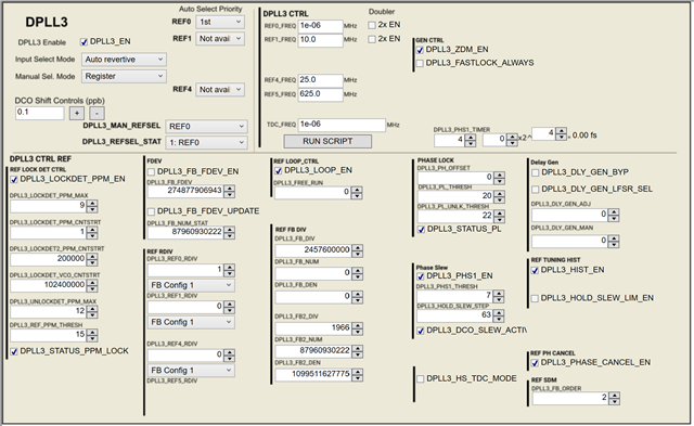
1) Set both DPLL2_REF0_RDIV and DPLL2_FB_DIV to 10, which means that the phasor frequency of the DPLL is 100mHz, but when configured, it was found that APLL2 and DPLL2 were configured with different VCO2 frequencies.

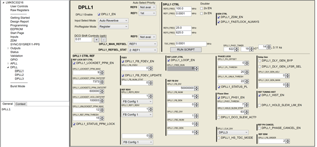
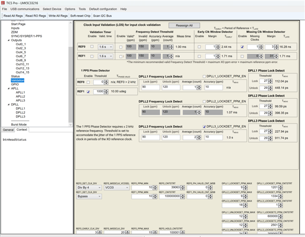
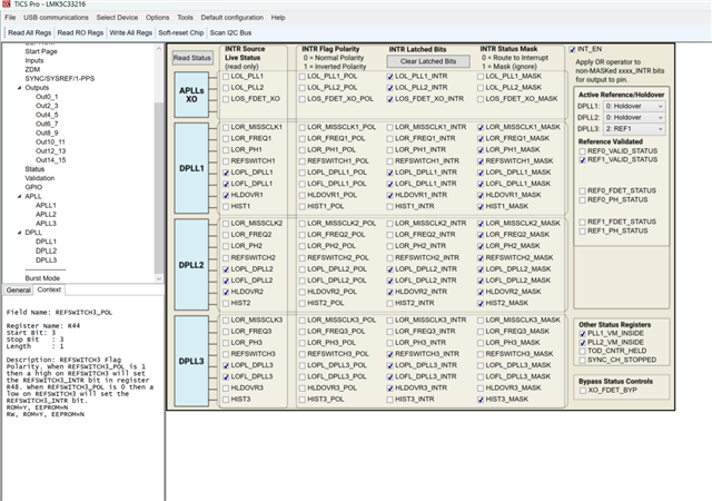
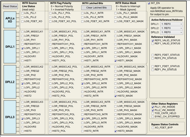
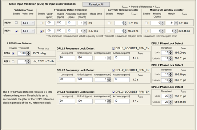
2) How to configure REF0 detection for 1 Hz? Both a 1-Hz square wave and sine wave were tried from REF0, but in the readback state, REF0_VALID_STATUS=0

3) What are the steps to configure the chip for a 1-PPS input? 

Could you help check this case? Thanks.

Best Regards,

Cherry

  • Hi Cherry,

    I have paged a device expert.

    3) What are the steps to configure the chip for a 1-PPS input? 

    To my knowledge, 1-PPS input requires turning on a special 1 PPS Phase Detector. This should be available in TICS Pro in the reference validation section, but I cannot confirm this at the moment because my LMK5C33216 profile seems to be corrupted. Do you have a working profile?

    Best,

    Evan Su

  • Hi Evan,

    Thanks for your support.

    REF0_PH_status is valid, but REF0_valid_status does not have a read back value.

    There are no working profiles available at this time, only APLL+DPLL configuration is complete. Configured as 1-PPS, readback status is displayed in holdover. Without giving a 1PPS reference, only ZDM mode, different reference clock and ZDM path tried, read back status LOPL and LOFL are set.

    Is there any register map and related report for ZDM mode and 1-PPS inputs available for reference? 

    Thanks and regards,

    Cherry

  • Hi Cherry,

    Sorry, I want to clarify that by "profile" I meant the LMK5C33216 profile in TICS Pro, which I assume you are using to configure the board because DPLL registers need MATLAB scripting and are too complex to calculate by hand. Can you share a screenshot of the reference validation settings?

    Is there any register map and related report for ZDM mode and 1-PPS inputs available for reference? 

    I do not have such reference information available. I think our device expert is still busy today but she would be able to generate a configuration for your case.

    Best,

    Evan Su

  • Hi Evan,

    Thank you for the clarification.

    And giving some updates:

    1) Customers have recently done some testing that references above 1KHz can be locked in ZDM mode, except DPLL1/2 has a longer lock time. But references below 1KHz don't work.

    The current configuration is approximately a 100 MHz XO, which is used as the clock source for APLL3 only. The clock source for APLL1/2 was from the VCBO mapping of APLL3. DPLL1/2/3 are enabled and all references are from IN1. DPLL1/2/3 ZDM from OUT0/4/10 respectively, target 1PPS reference can be locked. Currently, there are no trials that are successful from the development board.

    2) Also, references below 100KHz lock directly on the development board, but switch the configuration to their own clock board (reference development board design, just replace the controller with an MCU). After the configuration registers have been written (after step7), a reset is required to output the clock signal. Why is this? 

    3) 

    I want to clarify that by "profile" I meant the LMK5C33216 profile in TICS Pro, which I assume you are using to configure the board because DPLL registers need MATLAB scripting and are too complex to calculate by hand. Can you share a screenshot of the reference validation settings?

    The following is the configuration of the 100 Hz reference input being tuned, and the parameters of the DPLL are calculated using the matlab script:

    Thanks and regards,

    Cherry

  • Hi Cherry,

    It will take me until next week to look into this in detail. Please specify any timeline if urgent.

    Regards,

    Jennifer

  • Hi Jennifer,

    Thank you and expect your response.

    Reference over 1KZ the customer have been configured and are no problem, but their need is to reference 1-PPS. 

    Thanks and regards,

    Cherry

  • Hi,

    References below 1KHz cannot be locked, is there anything need to be taken care of? 

    Thanks and regards,

    Cherry

  • Hi Cherry,

    Jennifer is out of the office today but will get back to you next week.

    Best,

    Evan Su

  • Hi Cherry,

    After more testing, we've found that ZDM is not possible with 1-PPS. If they are looking for a deterministic phase relationship between 1-PPS input and output, then the LMK5C/B cannot support this. If they are trying to get phase synchronization but not deterministic between 1-PPS input and output, the LMK5C/5B can support.

    Regards,

    Jennifer

  • Hi Jennifer,

    Thank you for the help.

    If they are trying to get phase synchronization but not deterministic between 1-PPS input and output, the LMK5C/5B can support.

    Could you help share the sequence of configure registers and configuration captures?

    Are there special requirements for accuracy of the 1-PPS input clock? 

    The customer has tried not to use ZDM, the start page is as follows, calculated using the DPPL3 parameter executed by the matlab script: 

    The parameters for DPPL3 are as follows:

    The valid detection settings for the reference clock are as follows:

    Test result: 1-MHz output is visible on OUT0, but phase and frequency are not locked. The monitoring interface is as follows: 

    Thanks and regards,

    Cherry

  • Hi Cherry, 

    Please reduce the DPLL LBW to 0.1 Hz and hit Run Script again.

    I do not have a 1-PPS configuration for XO = 100 MHz at this time. However, you may use this one as reference to look at the Validation page settings which should match. In this config, REF0 is the 1-PPS signal.

    1-PPS, XO = 54 MHz_July 19 2023.tcs

    Regards,

    Jennifer

  • Hi Jennifer,

    Thank you very much for your patience and help.

    Refer to the provided configuration, use 38.88MHz XO, REF0 is the reference of 1-PPS. Modify according to the above requirements, the phase of DPLL has been locked, but LOPL has not been eliminated. Is there anything else that needs attention? If it is convenient, could you possibly to share a complete screenshot of the configuration parameters related to this function?

    The measured state readback is as follows, the three DPLL clock sources are all XO, and the REF are all 1-PPS square waves provided by the oscilloscope.

  • Hi Annie, 

    This helps narrow it down. Please try testing the following:

    1. Configure the GPIO pins to operate as TDC R and TDC FB dividers. These are the input the DPLL.
    2. Route them to the scope. Are they phase aligned or with some small, fixed phase offset? They should be triggered to each other on the scope and not drifting. It is okay if they are 180 deg out of phase with each other. Want it to look like this:
      1. If you do not see them triggered, please take a scope shot and post it here. That means the DPLL is not locked and the DPLL settings are incorrect.
    3. If you get a plot like the above, then we confirm that the DPLL is locked to the reference and we simply need to widen the LOPL thresholds more to make the LOPL_DPLL3 signal go low. In this case, you will need to increase these settings until you see LOPL go low:
  • Can you please also share the .tcs file they are using?

  • Hi Jennifer,

    1) 

    Can you please also share the .tcs file they are using?

    Please see here: https://e2echina.ti.com/cfs-file/__key/communityserver-discussions-components-files/124/3007.1_2D00_PPS_2C00_-XO-_3D00_38.88-MHz_5F00_July-26-2023.tcs

    we simply need to widen the LOPL thresholds more to make the LOPL_DPLL3 signal go low. In this case, you will need to increase these settings until you see LOPL go low:

    They've tried to adjust the the LOPL threshold but it does not help with the state cancellation of LOPL. 

    a. And also, there's a new finding, each time when reopen the software to modify the configuration, the script cannot be executed and it must be restored to default settings by default startup. 

    2) Could you help check are there other more clock chips that have been applied that support 1-PPS references? There is no other clock source in the customer’s application and clock synchronization can only be performed via GPS signal. A reference of 1-pps is preferred to lock the frequency and phase without input/output phase 0 delay or accurate delay. However, it is necessary to have a fixed relationship between the phase of the output and the reference at each power-up. 

    Thanks and regards,

    Cherry

  • Hi Cherry,

    1. Can you please attach the .tcs file to the e2e post? The link you shared is marked as restricted.

    2. The LMK5C supports 1-PPS references; however getting the register settings for this can take some time to get right.

    3. I'm also facing the TICSPRO Start Page errors as I work on getting the 1-pps settings. Please bare with me as I look into this further.

    4. What are the updates on routing the DPLL/TDC R and FB divider outputs? This is crucial for identifying if the DPLL settings are incorrect or if the DPLL_LOPL settings simply need to be adjusted.

    Regards,

    Jennifer

  • We are also having issues getting LMK5C33216EVM to correctly lock on to 1-PPS signal, with zero delay / phase aligned output PPS.  We need the 1-PPS output to be locked and zero phase offeset with incoming average GPS PPPS signal.  Using 52Mhz XO,  When the system comes out of holdover and PPS returned, we need to see the PSS output steer back into phase lock with average GPS PPS input BUT with controlled velocity and acceleration of phase change slew.  The datasheet doesn't go into detail, or we haven't found the answer yet.  If someone could help get us an initial tcs file to get started, we'd be a lot more inclined to use this chip in  our design.

  • Hi John,

    Let me check with the team if we have a 1-PPS + ZDM  .tcs file already made. If not, it will take a bit of time to get a configuration sent out. Please state your timeline requirements.

    Regards,

    Jennifer

  • Hi John,

    I confirmed again with the team that 1 PPS  + ZDM is not available on our LMK5C devices. This was also mentioned previously on this thread.

    Zero delay mode offers a deterministic phase offset at every power-up (in other words, the phase offset between 1 PPS and the outputs is the same each power-cycle).

    Using the DPLL without ZDM will provide the phase alignment between the 1-PPS and 1-PPS output. We also do have the phase slew option available which can be found in the DPLL page.

    Regards,

    Jennifer

  • It's not an overnight requirement, but if we can get this testing in the next few weeks that would be ideal.  Thanks.

  • Thanks, Jennifer.

    Do you have an example 1PPS tcs file without ZDM, but using the DPLL Holdover Exit Phase Slew controls - We need to understand how to set this up so when the system exits Holdover mode - and the GNSS PPS signal comes back:  When the output PPS is being brought back into phase with the input PPS signal, we need to see the output pulse steer into alignment at a rate of 20nsec per sec or slower.  We also need to know when the output PPS is back into alignment with the input PPS and all steering slew has stopped - is there a status bit that shows us when everything is locked and PPS aligned normal again after a holdover event? 

    Thanks,

    John

  • Hi John, 
    Jennifer is out of office and will be for the next few days. I have pinged another DPLL apps engineer to help support you. 

    Regards, 

    Vicente 

  • Hi John,

    I am back from being out of office. Let me set a dedicate time early next week to get this config going.

    Regards,

    Jennifer