Other Parts Discussed in Thread: LMX2594
This thread has been locked.
If you have a related question, please click the "Ask a related question" button in the top right corner. The newly created question will be automatically linked to this question.
Hi Osamu,
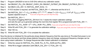
When you followed the instant calibration procedure, are you getting the lock detect at Step 1 before initializing the Instant cal?
If yes, after performing the sequence, are you getting the lock detect status at Step 8? If yes, then the instant cal procedure is done after Step 10 and you can write the settings for new frequency change.
Thanks!
Regards,
Ajeet Pal
Hi Osamu,
The given procedure in the above thread is the updated one from datasheet procedure (it is in progress to update in datasheet) and when you follow the same, PLL should lock the output at 5.65GHz in Step 1 and after performing the Instant cal procedure, the LUT generates at Step 10 with lock detect at 5.65GHz output frequency.
The last 2 steps are for the new frequency generation.
Thanks!
Regards,
Ajeet Pal
Hi Wada-san,
Could you provide your configuration for Step 1 in TICS Pro format?
Hi Ajeet,
I havedefault_test2.tcs attached the file to this message. Please check the contents.
Hi Wada-san,
The configuration looks fine except that the output frequency is 5650.0124MHz, but I think it should work.
Have you never get it lock to 5650.0124MHz?
Hi Noel,
After step1 finished, PLL locked to 5650.0124MHz. It worked fine until step10.
However, when the phase detector frequency was changed to 68.9146MHz and the PLL frequency was set to 5650.9MHz in steps 1 and 2 after initialization, the PLL did not lock.
Wada-san,
The instant calibration settings only apply to the phase detector frequency used to generate them. So if you generate the instant calibration table in with one phase detector frequency, but then change the phase detector frequency, it will not work.
Regards,
Dean
Hi Dean,
Thank you for your reply.
I thought 'To change frequencies after instant calibration is initialized' meant changing the phase detector frequency. Does this change the output frequency of the PLL?
When the last Steps 1 and 2 were performed, the PLL sometimes locked even when the phase detector frequency was changed, and sometimes it did not.
Regards,
Hi Wada-san,
When we change frequency, usually, we will change the N-divider value, channel divider value, phase detector frequency is usually fixed.
If you application requires changing fpd after instant calibration, I need to verify this operation again. I will get back to you on Friday.
Hi Wada-san,
I confirmed that after instant calibration is complete (Step 1 to 10), we need to keep the same fpd afterward. That means, after Step 1 to 10, when we are going to change the output frequency, we must keep fpd the same value that we used during instant calibration.
Why do you need to change fpd after instant calibration?
First, instant calibration is used because the target value of frequency switching time is strict. In addition, management of IBS and fractional spurious is complicated in fractional mode. For this reason, DDS is used to fine-tune the fpd, and the LMX2820 is operated in integer mode.
In such a configuration, what should be done to minimize the frequency switching time?
Hi Wada-san,
In this case, Instant Calibration cannot use, but you can still use full assist. Full assist operation is same as LMX2594, below is an appnote FYI.
Hi Noel,
Thank you very much for your advice.
I would like to ask you about the workflow in Fig 3-4 at the above URL.
Do the readback registers (rb_VCO_SEL, CAPCTRL, DACSET) change due to temperature, aging, etc.?
I'm concerned about whether the table should be created only at startup, or whether the table should be updated during use.
Regards,
Hi Wada-san,
CAPCTRL and DACISET may change at different temperature, VCO_SEL is not likely to change unless your frequency is right at the boundary of two adjacent VCO core.
Assuming you are not using any calibration assist. Now you start up and calibrate the device at a certain temperature. The device will lock and remains lock over the entire valid temperature range without a re-calibration. In this case, you are using the same calibration data over temperature. When you use this calibration data in full assist mode, the device will also remain lock over temperature.
For optimum performance, you may consider creating the LUT at different temperatures. BTW, each device should has its own LUT, because of part to part variation, don't use the same LUT for every device.