Other Parts Discussed in Thread: LMK04828
Hi team,
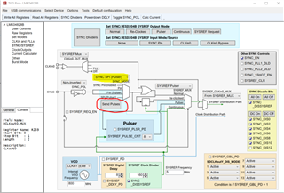
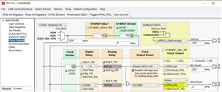
1) Using the LMK04828 direct divide function, the configuration is as follows:
R0 (INIT)	0x000090
R0	0x000004
R2	0x000200
R3	0x000306
R4	0x0004D0
R5	0x00055B
R6	0x000600
R12	0x000C51
R13	0x000D04
R256	0x010004
R257	0x010155
R258	0x010255
R259	0x010305
R260	0x010422
R261	0x010500
R262	0x010670
R263	0x010766
R264	0x010804
R265	0x010955
R266	0x010A55
R267	0x010BB5
R268	0x010C22
R269	0x010D00
R270	0x010E70
R271	0x010F66
R272	0x011004
R273	0x011155
R274	0x011255
R275	0x0113B5
R276	0x011402
R277	0x011500
R278	0x011670
R279	0x011765
R280	0x011804
R281	0x011955
R282	0x011A55
R283	0x011BB5
R284	0x011C22
R285	0x011D00
R286	0x011E70
R287	0x011F66
R288	0x012004
R289	0x012155
R290	0x012255
R291	0x0123B5
R292	0x012422
R293	0x012500
R294	0x012670
R295	0x012765
R296	0x012804
R297	0x012955
R298	0x012A55
R299	0x012B04
R300	0x012C22
R301	0x012D00
R302	0x012EE0
R303	0x012F66
R304	0x013001
R305	0x013155
R306	0x013255
R307	0x013305
R308	0x013463
R309	0x013510
R310	0x013620
R311	0x013766
R312	0x013845
R313	0x013902
R314	0x013A00
R315	0x013BA0
R316	0x013C00
R317	0x013D08
R318	0x013E03
R319	0x013F04
R320	0x0140E0
R321	0x014140
R322	0x014200
R323	0x014313
R324	0x0144BF
R325	0x01457F
R326	0x014611
R327	0x014710
R328	0x014802
R329	0x014942
R330	0x014A02
R331	0x014B02
R332	0x014C00
R333	0x014D00
R334	0x014EC0
R335	0x014F7F
R336	0x015003
R337	0x015102
R338	0x015200
R339	0x015300
R340	0x01540A
R341	0x015500
R342	0x015614
R343	0x015700
R344	0x015896
R345	0x015900
R346	0x015A05
R347	0x015BD3
R348	0x015C20
R349	0x015D00
R350	0x015E00
R351	0x015F0B
R352	0x016000
R353	0x016105
R354	0x016245
R355	0x016300
R356	0x016400
R357	0x01650F
R369	0x0171AA
R370	0x017202
R380	0x017C15
R381	0x017D33
R358	0x016600
R359	0x016700
R360	0x016820
R361	0x016959
R362	0x016A20
R363	0x016B00
R364	0x016C00
R365	0x016D00
R366	0x016E13
R371	0x017320
R386	0x018200
R387	0x018300
R388	0x018400
R389	0x018500
R392	0x018800
R393	0x018900
R394	0x018A00
R395	0x018B00
R8189	0x1FFD00
R8190	0x1FFE00
R8191	0x1FFF53
800M input, 200M and 5M output, no output is tested at this time. The 1-M square wave signal is given by the FPGA at sync. The customer want to use a divide to achieve 8 pulse output, but the current configuration can only test one low signal.
Could you help check the above configuration? And how to implement pulse output?
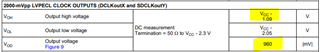
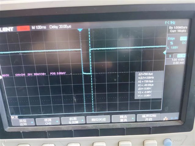
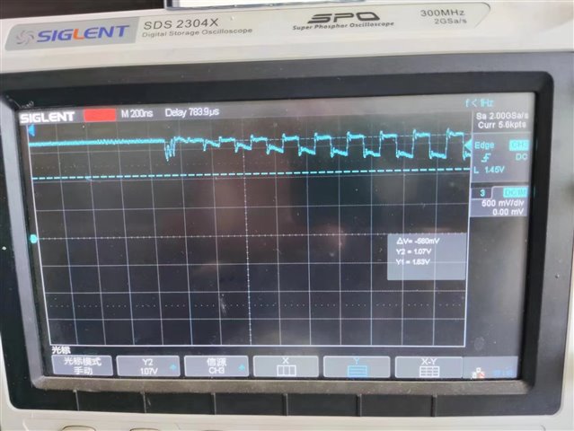
2) The pulse signal can be output using the internal VCO, and the output waveform is as follows:

The amplitude of the waveform has a larger ringing and the signal amplitude is smaller. Why's this?
3) In SYSREF continuous output mode, all registers are configured and after 2 seconds are output, directly by configuring 0x013621→0x013620. The output goes from off (PD) to on. The test results are as follows, and the output is a little strange:
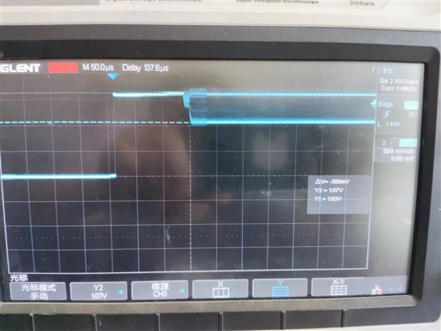
Could you help check this case? Thanks.
Best Regards,
Cherry