This thread has been locked.

If you have a related question, please click the "Ask a related question" button in the top right corner. The newly created question will be automatically linked to this question.

LMX2594EVM: spurs issue

Part Number: LMX2594EVM
Other Parts Discussed in Thread: PLLATINUMSIM-SW

Hi team,

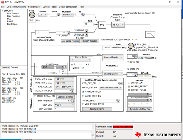
When the denominator is used to its maximum, there are spurs at many frequency points. But some of the frequency points have no spurs. How to avoid fractional spurs by changing the denominator? 

Could you help check this case? Thanks.

Best Regards,

Cherry

  • Hi Cherry, 
    We will look into this tomorrow. 

    Regards, 

    Vicente

  • Cherry,

    This spur looks very close to 109/125.  With Fpd=100MHz, this would generate spurs at 100/125 = 0.8 MHz increments and no sub-fractional spurs.

    However, expressing this as a larger unequivalent fraction would just make spurs worse.

    What you are seeing is that the impact of using these larger unequivalent fractions.  

    Think of it this way:

    Period of phase detector  = 1/100 MHz = 10 ns

    Fractional Denominator:  4294967295

    Note that this is divisible by 3, so fractional sequence length is:

    1st & 2nd order Modulator:  4294967295

    3rd & 4th Order Modulator:  4294967295 x 3

    You have the 3rd order modulator, so the repeat length of this sequence is:

    4294967295 x 3 x 10 ns = 128 seconds

    In other words, you can see it.  You can reduce the modulator order to 2nd order and you will see it goes 3x faster.

    Also, if you were to choose a different denominator that was not divisible by 2 or 3, it would also be 3x faster, i.e. you can try 4294967293

    But unless you really need this fractional resolution, I would consider expressing the fraction in simpler terms.

    Also, PLLatinum sim tool at ti.com/tool/PLLATINUMSIM-SW models spurs.  In this case, you would model as a fraction of 1/5 and say 100% randominzation.

    Regards,

    Dean

  • Hi Dean,

    Thank you for the detailed response.

    Adjusting the modulation order and denominator as described above can indeed change the spurs running speed, as described by you. The frequency accuracy requirement is Hz or 10Hz level, the customer has tried to change the denominator to 2^23, or to divide the numerator and denominator by approximately from 429467295. The phenomenon is that the spurs of the run have become smaller in magnitude, and the frequency points of occurrence have been reduced, but they still exist.

    1) For large denominator, can the runaway spurs only be decreased and not be eliminated?

    2) How should it be reasonable to choose the denominator for avoiding the spurs of running? 

    Thanks and regards,

    Cherry

  • Cherry,

    1)  For large denominators that do not reduce, these "runaway spurs" will exist.  This is because the repeat length of the sequence is so long that you can visually see it.  So so this is a consideration when creating large denominators ( like 1000000/4000001 instead of 1/4) when then are not necessary bring this on.  For example, in the above example, you have the fraction of 3745211481 / 4294967295 to get an output of 10187.1999999994.  But is this what you really want, or do you really want 109/125, which would give an output of 10187.2  .  The fraction of 109/125 would have way better spurs in all regards.

    Your fraction is about 1/5, which is pretty reasonable.  If it was close to 0, 1, or 1/2 the spurs might get worse

    2)  Aside from not using larger fractions, I do think the choice of fraction might have an impact as well.  If you want large fractions you might also try not using the entire numerator, suppose you choose a fractional denominator of 100000000 or 10000001, this would have a much faster repeat rate.

    Realize that even for a fraction like 17/100, there is actually a walking spur, but because the spur is walking so fast, the loop filter can track it out.  It is only in this case where the spur frequency is low that you see the walking spur.

  • Hi Dean,

    For running spurs, by changing the denominator and changing the MASH_ORDER to 4th order, it seems that it is no longer visible.

    But changing MASH_ORDER to 4th order deteriorates the phase noise. The customer wants to optimize by changing the phase detection frequency to 200MHz, but finds that the phase noise of the point in the front picture is abnormal, -98dBc/Hz@10KHz (100MHz phase detection frequency, mash_order: 4th order, phase noise is -114dBc/Hz@10KHz). But other points are normal (for example around 3.4G). At the same time, in the past use process, it is also found that some frequency points cannot be locked when using 200MHz phase detection. 

    Would you have any suggestion for above two questions?

    Regards,

    Annie

  • For the 4th order modulator, the minimum N divide is 40.  So for VCO frequencies below 8 GHz, it violates this constraint.  So this is perhaps the issue with the locking.  For lower order modulators, the minimum N divide is lower.

    Higher phase detector frequency will push out the MASH energy to higher frequencies, so is generally beneficial.

    Also, realize that if you increase the phase detector from 100 MHz to 200 MHz, this alters the loop bandwidth, unless the loop filter components are changed.  To preserve the same loop bandwidth without changing the loop filter, you can simultaneously decrease the charge pump gain by 50% to keep the same loop bandwidth and phase margin.

    Regards

    Dean