This thread has been locked.

If you have a related question, please click the "Ask a related question" button in the top right corner. The newly created question will be automatically linked to this question.

LMK05318: Output waveform is gated, not continuous

Part Number: LMK05318

Hi,

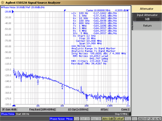
I configured a 10 MHz output :  

Observing the waveform : 

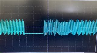
Question : The 10 MHz is correct, but the waveform is gated in period of around 0.5 second ( muted around 0.2 second ) ? How can I get a ontinuous output ? Thanks.

  • Hi,

    • Please share the .tcs file and elaborate on the conditions of the scope shot.
    • Is this after hitting soft-reset, power-up, or loading a configuration?

    Regards,

    Jennifer

  • Hi Jennifer,

       Following is the .tcs file. 

       The scope shot is the waveform of CH6 OUT6_P, OUT6_N is floating.  1V/DIV and 50ms/DIV.  

       If zoom in with 100ns/DIV, it is a 10MHz sine wave. The problem is : there is a muted period for every ~0.5 second shown is the middle of scope shot.

       It is a stable waveform after configuration ( programing the registers with a MCU via I2C after power on). 


    UDC LMK05318 0719.tcs

  • Hi Martin, 

    • Are you using your custom board or the LMK05318(B) EVM?
    • Is this the LMK05318 (non-B) or LMK05318B?
    • Do you mean the muted period goes away after programming with I2C? If you don't program, the muted period continuouslyshows up every 0.5 s?
    • If you soft-reset or power cycle the board, does that help prevent the continous muted period from showing up?

    Regards,

    Jennifer

  • Hi Jennifer,

      1. Using custom board

      2. without B

      3. The muted period show up both before and after programming with I2C. If I don't progrm, the muted period still shows up. It is quite interesting because I never program the EEPROM. The EEPROM is empty, If I don't program, how are the register values loaded ? (HW_SW_CTRL=1)

      4. Soft-reset or power cycle does not prevent the coutinuous muted period showing up.

    Regards,

    Martin

  • Martin,

    The EEPROM is not empty. There is a default configuration. Details are listed in the datasheet page 65.

    1. Is there another board you can test to see if it has the same issue?
    2. If waveform is unstable before and after programming, what do you mean by "it is a stable waveform after configuration ( programing the registers with a MCU via I2C after power on)"? 

      1. Do you mean that programming with TICSPRO causes the unstable waveform? Or when you say program do you mean EEPROM programming?

    Regards,

    Jennifer

  • Jennifer,


    The EEPROM is not empty. There is a default configuration. Details are listed in the datasheet page 65.

    => This means that LMK05318 load default configuration and then generate 10M gated waveform on OUT6_P. This is weird ...

    1. Is there another board you can test to see if it has the same issue?

    => Yes, I will do more test.

    1. If waveform is unstable before and after programming, what do you mean by "it is a stable waveform after configuration ( programing the registers with a MCU via I2C after power on)"? 

      1. Do you mean that programming with TICSPRO causes the unstable waveform? Or when you say program do you mean EEPROM programming?

    => The "stable waveform" means that muted period appears stably and looks like an intentional behavior.

    Is it possible that some event causes LMK05318 mute output and reboot ?    

    Regards,

    Martin

  • Jennifer,

       Above problem is has been fixed. It is cuased by a firmware bug : the MCU watchdog timer was enabled incidentally.

       I can see continuous 10MHz signal on OUT6_P. However, with same output configuration, there is no 10MHz signal on OUT5_P. Could you please check if there is anything wrong ? Thanks. I attached my tcs file again. Thanks. UDC LMK05318 0722.tcs

  • Hi Martin,

    I can see an output at OUT5 and OUT6. Please try hitting "Soft Reset" in the tool bar. 

    I reviewed and test your file. The only concern I have is that you are using a 10 MHz input for the XO pins. This causes issues if you have the DPLL enabled because the VCO1 will have an integer relationship with the XO and cause integer boundary spurs (IBS). We recommend values such as 24, 38.88, 48, 54 MHz instead.

    Regards,

    Jennifer

  • Hi Jennifer,

       Thanks a lot for your help and advice.

    Martin