This thread has been locked.

If you have a related question, please click the "Ask a related question" button in the top right corner. The newly created question will be automatically linked to this question.

LMK05318: Application issue

Part Number: LMK05318
Other Parts Discussed in Thread: LMK5C33216, LMK5B33216

Hi Team,

The customer would like to use LMK05318 example for 1588 synchronization scheme and please see the following diagram for details.
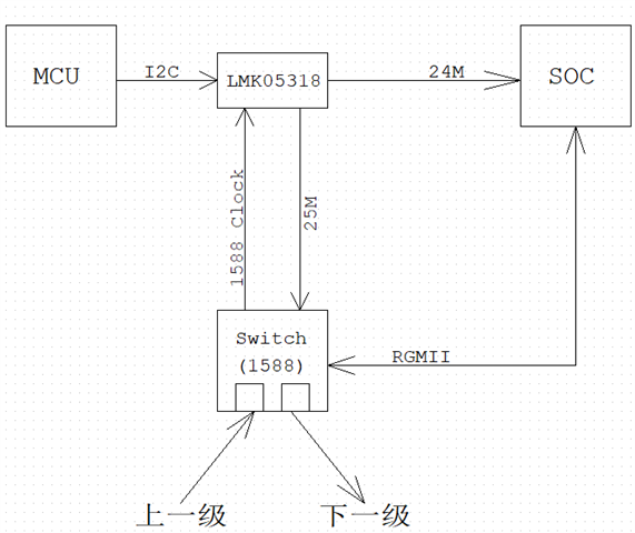
The consumer's goal is to synchronize these N devices with 1588.

The switch recovers 1588 clock from the previous stage, output to the reference clock input of the LMK05318, and the two output clocks of the LMK05318 (25M and 24M) are automatically synchronized to 1588 clock (sync frequency and phase), could you help tell if the above understanding correct or not? 

1) Can the LMK05318 synchronize frequency lock and phase lock of 1588 clock on the switch output?

2) Is there a special software algorithm to adjust the output synchronization frequency of the LMK05318?

3) Is the above solution feasible? If possible, what is the synchronization accuracy? 

Could you help check this case? Thanks.

Best Regards,

Cherry

  • Hello,

    1) Can the LMK05318 synchronize frequency lock and phase lock of 1588 clock on the switch output?

    Provided the 1588 clock is an acceptable input frequency, then yes.  The LMK05318 can frequency and phase lock to this input frequency.

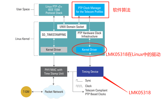
    However, when locking by PTP, it is not necessary to have an "input clock."  It is possible for the LMK05318 to lock to some stable frequency reference, then the PTP algorithm will send commands to DCO the PLL up/down to be frequency/phase locked.

    Sometimes the PLL will lock to a frequency reference clock, the using DCO to perform phase alignment.

    2) Is there a special software algorithm to adjust the output synchronization frequency of the LMK05318?

    Above I mention that DCOing the LMK is how PTP would be done.  The software algorithm would take the PTP info, the phase/frequency information from the LMK05318, then make appropriate DPLL adjustments.

    Two things.

    (1) The LMK05318 requires an XO input frequency to run the APLLs and provide 'holdover' frequency accuracy if the DPLL input is lost.  The LMK05318 DCO is applied to the DPLL.  Which means you need an input reference is not able to make DCO adjustments with no DPLL input.  So a typical configuration would be to have a frequency accurate clock for the DPLL to lock to, for example SyncE reference or OCXO.  Then you may have an XO/TCXO/or OCXO (if not using OCXO on input) on the 'XO' APLL reference - you would choose the "XO technology" depending on (i) the holdover performance you want and (ii) a function of how narrow you'd like DPLL loop bandwidth to be - generally you'll want to use a TCXO or OCXO for DPLL loop bandwidths less than 10 Hz.

    (2) The LMK5B33216/414 and LMK5C33216 can perform DCO without a DPLL reference input.  So you could simply lock the APLL to the XO input, then provide DCO updates to the APLL directly (or DPLL as in LMK05318).

    73,
    Timothy

  • Hi Timothy,

    Thank you for the support.

    then the PTP algorithm will send commands to DCO the PLL up/down to be frequency/phase locked.

    May I know where to get the PTP algorithm?

    Could you help tell how to get the software algorithm? Is the lmk05318 driver code in Linux available through the GUI tools provided by TI? 

    Thanks and regards,

    Cherry

  • Hello Cherry,

    PTP stack is provided through partnering with TI, we will customize the PTP stack according to your architecture and timing accuracy requirements. Can you please send an email to k-mandoth@ti.com? I need to know the project details and few spec requirements that you need with PTP stack. 

    Thanks,

    Kumarpal.