This thread has been locked.

If you have a related question, please click the "Ask a related question" button in the top right corner. The newly created question will be automatically linked to this question.

TLC555: Frequency deviation from set value

Part Number: TLC555

Hi team,

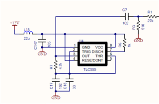
I made the attached schematic with a TLC555, but the frequency is not near the 145kHz I set.
I used a capacitor with a tolerance of less than 5%, but the frequency varied between 90kHz and 120kHz.
This variation depends on the IC, if only the IC is changed in the two circuits, the deviation will be dependent on the IC.
At 120KHz, Duty is around 50%. At 90KHz, 100KHz, etc., the duty cycle will be around 60% HighDuty. and the Low time is the same as at 120KHz.
Does IC cause such a discrepancy?
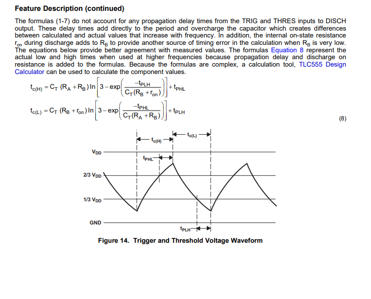
I don't think there was such a discrepancy when I used the calculation tool.

  • Hi Ryu, 

    Does IC cause such a discrepancy?

    Regarding to the LTC555 will cause the discrepancy, I would check it with Chris, who understands the timers' history better than I do.


    You would need to deQue the LC filters for your 12Vdc supply. Is there a reason that you configure the fr (resonance frequency) near 34kHz? If the 12Vdc is from a switching power supply, what is the switching frequency from AC/DC or DC/DC converter.  If you set the pole near 5kHz or 1kHz, it may be good enough. There is a possibility that the switching frequency of 12Vdc and Q of the LC filter are interfering with the 555's timer's charging/discharging events. 

    If you want to deQue the supply better, than you may use the following similar techniques, see the simulation. 

    Deque LC Supply rail 08242023.TSC

    Best.

    Raymond

  • Hey Ryu, 

    The max frequency is a typical of 2.1MHz. The minimum is 1.2MHz meaning that if you take a distribution of devices then you will see a spread of the maximum operating frequency anywhere from 1.2MHz to 2.1MHz. It is very difficult to achieve accurate results above 100kHz and you must use the equations in the PDS that account for propagation delays in order to estimate the timing. These equations are shown on page 17. I have found the propagation delays on the units I measured to be 215ns for both TPHL and TPLH. The values can vary up to 30%. 

    Below you can see that there is significant curvature (non-linear) behavior at frequencies above 100kHz and the timing capacitor needs to be small for high frequencies. For this reason the tolerance of the capacitor must be well controlled and board parasitic capacitance must be accounted for. My recommendation is to use an LCR meter to measure the timing capacitor at the frequency of interest and also measure the board parasitic capacitance with the TLC555 removed from the board. This will give the most accurate result in the equations when plugging in this total capacitance for CT. My recommendation is to use these equations in excel and plugin the real measured values. In addition you should account for the tolerances of components stated from the manufacturer. The timing capacitor is critical and should be film or COG/NPO. The tolerance of the capacitor will be given as 5% in some cases but it is important to measure at the frequency of interest as well to get an accurate value to plug in.  I have attached my example calculator with some values already plugged in for demonstration such as the propagation delays and board parasitic capacitance of my board. See the excel sheet below. Lastly, in the calculator I also calculate the duty cycle at the particular frequencies. You will notice that it is roughly a 60% duty cycle in this case. 

    There are some general best practice guidelines to follow for minimizing parasitic capacitance in the layout of the PCB.

    1. Increasing space between adjacent traces
    2. Cutting out power and ground planes above and below critical traces
    3. Minimizing component to component trace lengths. Shorter traces will have less capacitance due to capacitance per unit length.
    4. Minimizing use of Vias on critical traces.

    TLC555 Equations (1).xlsx

    Best Regards, 

    Chris Featherstone

  • Hi Raymond,

    Thanks for the reply.
    I understand about the LC filter.

    Best.

    Ryu

  • Hi Chris,

    Thank you for the details.
    I have found it difficult to set 150 kHz with this device.
    I will try to measure the capacitance value accurately.
    Also, do you have any recommendations for a device to set around 150 kHz?

    Best,

    Ryu

  • Hey Ryu, 

    One alternative could be a smart DAC. Here are the trade offs compared to a 555 timer. I have linked an application note below as well. 

    https://www.ti.com/lit/an/slaae33/slaae33.pdf?ts=1692218106536&ref_url=https%253A%252F%252Fwww.google.com%252F

    Best Regards, 

    Chris Featherstone