Part Number: SE555
Other Parts Discussed in Thread: NE555
Hello All,
My summer homework is a linearly proportional capacitance-to-frequency converter like a capacitance meter.
The capacitance to be measured is 10-500pF, the value of the output frequency is indifferent, it can be anything, but it must be linear.
I would like to solve this with a triangular wave generator, as far as I know its frequency is linearly proportional to the capacity.
The conventional integrator-comparator topology cannot be used because one point of the capacitance is must be grounded.
I want to use the Texas Instruments SE555 IC, but it does not work properly with such small capacitances.
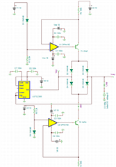
Two current generators charge and discharge the capacitor through a diode bridge. The charge-discharge is controlled by the NE555, also through the diode bridge.
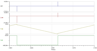
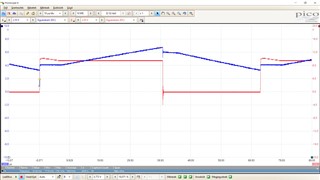
The problem can be seen on the oscilloscope, there is a sudden level drop at the beginning of the discharge, the beginning of the discharge shows abnormal operation.
The blue ray is the voltage of the capacitor, the red is the output of the SE555.
The same can be seen at the beginning of the charging phase. This phenomenon is not observed if the capacitance value is a few nanofarads or higher.
I tried two current generator settings, ~6uA and ~12uA, the result is the same. The currents of the current generators are exactly the same.
I would like to ask for your help, what can cause this, what am I doing wrong, what is avoiding my attention?
The schematic diagram is attached, the supply voltage is 10V, the current generator is an AD823 dual opamp, unfortunately I don't have TI opamp at the moment.

Thanks in advance, Zoltan