Hi, I am using CDCEL937-Q1 clock buffer for our project.
According to the datasheet S1 and S2 pins will act as I2C SDA and SCL as default.
If i try to read any register of Generic configuration registers,I am getting value as 0x07 for all the register read. I didn't get any default value as mentioned in the datasheet.
Whether any other process need to be done to read/write registers value.
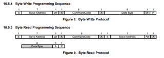
For example: I am trying to read register 0x01, as this is byte read, command code will be 0x81, and slave address is 0xDB and I am following the byte read steps as given in the datasheet, still i didn't get default value as mentioned in the datasheet. If i write the register and read back it, still i am getting a 0x07 value.
Can you please send the steps for register read/write ?


