This thread has been locked.

If you have a related question, please click the "Ask a related question" button in the top right corner. The newly created question will be automatically linked to this question.

LMK04828: The digital delay function cannot be used

Part Number: LMK04828
Other Parts Discussed in Thread: LMK04832

Hi Team,

The customer is trying to validate the digital and analogue delays for lmk04828.

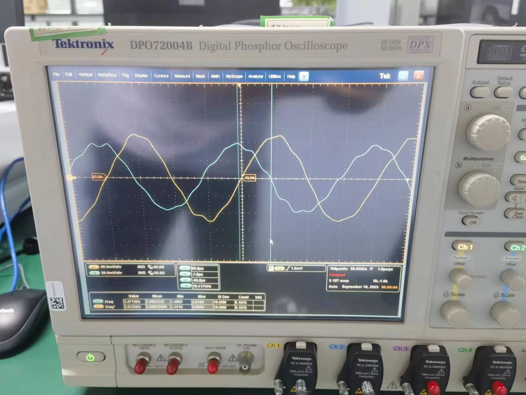
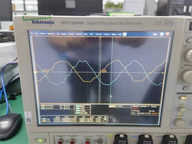
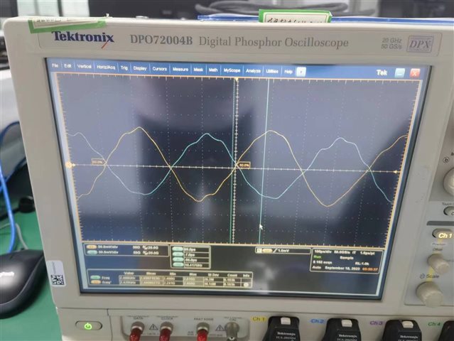
The clkin1 input is a 20 MHz clock and the oscin input is a 100 MHz clock. Vco0 is 2500 MHz. Dclkout0 is 2500 MHz, dclkout2 is 2500 MHz. An oscilloscope is used to test the delay of these two clocks.

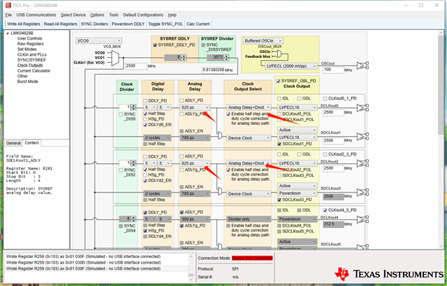
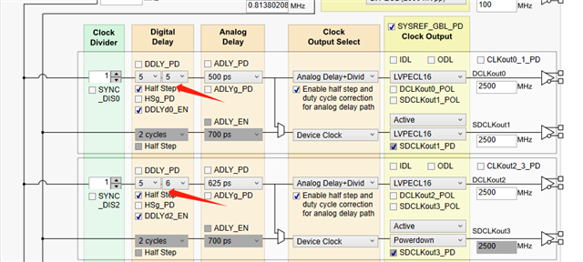
Regarding Analogue delay: Set clock output select to analogue delay + divider on TICSPRO. After the chip configuration is complete, change the delay value in analogue delay to see that the clock delay did change, but the changed value and the set value are different. 

Regarding to the digital delay function, it has two modes according to the manual:

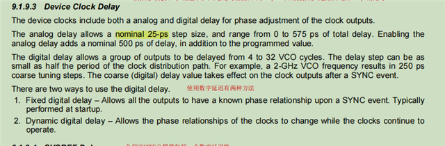
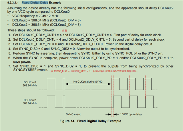
The customer is attempted to use the example on the manual to verify the Fixed Digital delay:

  • Set DCLKout0_DDLY_CNTH/L to a value of 4,4;
  • Set DCLKout0_DDLY_CNTH/L to a value of 4,5;
  • Set DCLKout0_DDLY_PD = 0 and DCLKout2_DDLY_PD = 0;
  • Set sync_DIS0 = 0 and sync_DIS2 = 0;
  • Then sync_pol write 1 and then 0.

VCO0 is known to be 2500 MHz. The modified delay is half a VCO0 cycle, that is, it should be 200 ps, which means dclkout0 and dclkout1 should be inverted. But the output clock doesn't change in reality. 

Could you help look into this case? Thanks.

Best Regards,

Cherry

  • Hi Cherry, 

    I’ll provide an update by end of this week. 

    Regards,

    vicente

  • Hi Vicente,

    Thank you for the support and expect the updates!

    Thanks and regards,

    Cherry

  • Hi Cherry, 
    I have gone in lab and confirmed the digital delay step size is correct on Scope. 

    Can you please provide more info about customer procedure and how they're testing this? 

    Regards, 

    Vicente 

  • Hi Vincente,

    The register configuration is as follows:

    R0 (INIT)	0x000090
    R0	0x000010
    R2	0x000200
    R3	0x000306
    R4	0x0004D0
    R5	0x00055B
    R6	0x000600
    R12	0x000C51
    R13	0x000D04
    R256	0x010001
    R257	0x010155
    R258	0x010255
    R259	0x01030F
    R260	0x010442
    R261	0x010500
    R262	0x010601
    R263	0x010755
    R264	0x010801
    R265	0x010955
    R266	0x010A55
    R267	0x010B2F
    R268	0x010C42
    R269	0x010D00
    R270	0x010E01
    R271	0x010F05
    R272	0x011008
    R273	0x011155
    R274	0x011255
    R275	0x011300
    R276	0x011402
    R277	0x011500
    R278	0x0116F9
    R279	0x011700
    R280	0x011818
    R281	0x011955
    R282	0x011A55
    R283	0x011B00
    R284	0x011C02
    R285	0x011D00
    R286	0x011EF1
    R287	0x011F33
    R288	0x012008
    R289	0x012155
    R290	0x012255
    R291	0x012300
    R292	0x012402
    R293	0x012500
    R294	0x0126F9
    R295	0x012700
    R296	0x012808
    R297	0x012955
    R298	0x012A55
    R299	0x012B00
    R300	0x012C02
    R301	0x012D00
    R302	0x012EF9
    R303	0x012F00
    R304	0x013006
    R305	0x013155
    R306	0x013255
    R307	0x013300
    R308	0x013402
    R309	0x013500
    R310	0x0136F1
    R311	0x013733
    R312	0x013805
    R313	0x013900
    R314	0x013A0C
    R315	0x013B00
    R316	0x013C00
    R317	0x013D08
    R318	0x013E03
    R319	0x013F00
    R320	0x01400F
    R321	0x014103
    R322	0x014200
    R323	0x014311
    R324	0x014400
    R325	0x01457F
    R326	0x014618
    R327	0x01471A
    R328	0x014802
    R329	0x014942
    R330	0x014A02
    R331	0x014B16
    R332	0x014C00
    R333	0x014D00
    R334	0x014EC0
    R335	0x014F7F
    R336	0x015003
    R337	0x015102
    R338	0x015200
    R339	0x015300
    R340	0x015478
    R341	0x015500
    R342	0x015678
    R343	0x015700
    R344	0x015896
    R345	0x015902
    R346	0x015A58
    R347	0x015BD4
    R348	0x015C20
    R349	0x015D00
    R350	0x015E00
    R351	0x015F0B
    R352	0x016000
    R353	0x01610A
    R354	0x016244
    R355	0x016300
    R356	0x016400
    R357	0x01657D
    R369	0x0171AA
    R370	0x017202
    R380	0x017C15
    R381	0x017D33
    R358	0x016600
    R359	0x016700
    R360	0x01687D
    R361	0x016959
    R362	0x016A20
    R363	0x016B00
    R364	0x016C00
    R365	0x016D00
    R366	0x016E13
    R371	0x017300
    R386	0x018200
    R387	0x018300
    R388	0x018400
    R389	0x018500
    R392	0x018800
    R393	0x018900
    R394	0x018A00
    R395	0x018B00
    R8189	0x1FFD00
    R8190	0x1FFE00
    R8191	0x1FFF53

    The following are the analogue delays tested using an oscilloscope. Adjustments can be made, but the values appear to be incorrect. There is still a problem with using the digital delay feature. Would it be possible to share your register configuration? 

    Thanks and regards,

    Cherry

  • Hello Cherry,

    Is the problem only seen on the fixed digital delay feature, or is it also seen when only setting the analog delay setup? I am currently working on debugging this issue in the lab and should get back to you by Wednesday. If you have any updates do let me know.

    Best,

    Andrea

  • Hello Cherry,

    Analog delay can only be used for outputs with a maximum frequency of 1536-MHz; therefore, since you are operating at 2500-MHz, analog delay won't work.

    However, are you trying to delay CLKout0 and CLKout2 by 100-ps? Basically, if you tell me the different delays you are trying to achieve between your outputs, I may be able to suggest another delay feature that can achieve that for you if the part has that capability, or recommend another similar part.

    Apart from this, I tested both outputs at 1024-MHz without any delays, synced them, used phase-matched/same-length cables, and still saw a ~50-ps delay between them (picture showing this below, note that I used a different VCO frequency since I'm using a 122.88-MHz VCXO). I'm contacting other people in my team to see if this is expected, which may be the reason why you are not seeing the exact delay between your outputs, even when operating the outputs within the allowed frequencies.

    Also, how come you are using delays for your outputs? Ii would be great to learn more about your system so I can better support you.

    Best,

    Andrea

  • Hi Andrea,

    Thanks for your support!

    are you trying to delay CLKout0 and CLKout2 by 100-ps?

    Yes, and the frequency of the clk0 and clk2 outputs is 2500 MHz. 

    how come you are using delays for your outputs?

    The reason why they use the delay function is that the subsequent system had clock requirements, and the customer are debugging this function now.

    I'm contacting other people in my team to see if this is expected, which may be the reason why you are not seeing the exact delay between your outputs, even when operating the outputs within the allowed frequencies.

    Thanks and expect the updates.

    Thanks and regards,

    Cherry

  • Hello Cherry,

    Yes, and the frequency of the clk0 and clk2 outputs is 2500 MHz. 

    Because the maximum frequency for analog delay is 1536-MHz for the LMK04828, analog delay cannot be used for the 2500-MHz outputs. Without using analog delay, the smallest delay the LMK04828 can generate is half a VCO cycle; therefore, for this application, the smallest delay step size possible would be 200-ps (1/2500MHz/2 = 200ps). This means the required step size of 100-ps cannot be achieved using the LMK04828. However, the LMK04832 can use analog delay for all the output frequencies it offers, and therefore, it would a device to consider if the 100-ps delay is necessary. Note that the LMK04828 and the LMK04832 are similar devices.

    The reason why they use the delay function is that the subsequent system had clock requirements, and the customer are debugging this function now

    This is still a bit vague and still makes it harder for me to understand the system and why those requirements exist. If possible, please email me with more specifics of their system if you don't want to share it in the public forum.

    expect the updates.

    I just spoke with my team member and after reviewing the data sheet together, the 50-ps skew between outputs is a typical spec for the LMK04828. Therefore, if the application requires an absolute skew of 100-ps, please take this into account as well. If an absolute skew measurement is not required, then we generally recommend customers to add a skew on the scopes to physically aligned outputs on the scope.

    Hope this helps and do let me know if I didn't answer all your questions.

    Good luck,

    Andrea