This thread has been locked.

If you have a related question, please click the "Ask a related question" button in the top right corner. The newly created question will be automatically linked to this question.

LMK04832: Shift phase dynamically by Dynamic Digital Delay

Part Number: LMK04832

Hi team,


Customer generate 6GHz CLK with LMK04832 by the below methodology.

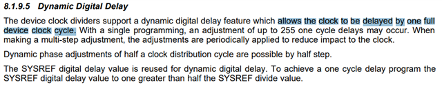
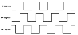
  1. Shift phase with half CLK against reference CLK.
  2. Shift phase dynamically between same phase and shifted phase with half CLK.

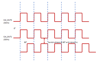
Regarding the above inquiry, is it possible with LMK04832 Dynamic Digital Delay ?

Thank you and best regards,

Michiaki Tanii

  • Hello Michiaki,

    If using dynamic digital delay, then the minimum delay you can do is by half a VCO cycle (note that you need to use the half step feature for this); therefore, if the VCO frequency is a multiple of the reference frequency, then the phases can be adjusted dynamically. However, to better help you/corroborate this, please tell me more about your system, your goals with your delays/why you need to delay your outputs, and the exact frequencies you're working with. If you have a .tcs file, please also attach it. Thanks!

    Best,

    Andrea

  • Hi Andrea,

    For example to understand easily, in case of CLKout at 3GHz, customer can select VCO frequency = 3GHz, reference frequency = 250MHz with half step function using Dynamic Digital Delay for the dynamic phase shift at 90° ?

    Thank you and best regards,

    Michiaki Tanii

  • Hello Michiaki,

    Note that the LMK04832 cannot output 6-GHz; therefore, if you are trying to output this frequency, you would need one of our RF PLL & Synthesizers that can handle those higher frequencies. If you are trying to delay a 3-GHz output clock by and shift another 3-GHz output clock by 90 degrees phase shift, this can be done with the LMK04832. Hope this helps!

    Good luck,

    Andrea

  • Hi Andrea,


    We want your clear yes, no answer to clarify if our understanding is correct or not at first.

    For the below example, is our understanding correct ?

    ------------

    For example to understand easily, in case of CLKout at 3GHz, customer can select VCO frequency = 3GHz, reference frequency = 250MHz with half step function using Dynamic Digital Delay for the dynamic phase shift at 90° ?

    ------------


    For the 6GHz output operation which your point out, customer understand LMK04832 doesn’t support 6GHz but they want to know if the device can work pseudo 6GHz by shifting 90 degree phase because the device has already been used in another project.


    Your understanding would be highly appreciated.

    Michiaki Tanii

  • Hello Michiaki,

    I want to clarify, are trying to achieve a 180 degree phase shift or 90 degree phase shift? Your diagram shows a 180 degree phase shift (refer to diagram below):

    For example to understand easily, in case of CLKout at 3GHz, customer can select VCO frequency = 3GHz, reference frequency = 250MHz with half step function using Dynamic Digital Delay for the dynamic phase shift at 90° ?

    This assumption is correct if you meant 180 degrees instead of 90 degrees and the phase shift is done tot he 3-GHz signal. Basically, this is the correct statement: "...in case of CLKout at 3GHz, customer can select VCO frequency = 3GHz, reference frequency = 250MHz, and set another CLKout with half step function using Dynamic Digital Delay for the dynamic phase shift of 180° from the 3-GHZ CLKout"

    For the 6GHz output operation which your point out, customer understand LMK04832 doesn’t support 6GHz but they want to know if the device can work pseudo 6GHz by shifting 90 degree phase because the device has already been used in another project.

    How is the customer aiming to achieve this, i.e create a clock from two CLKouts of the LMK04832? I am curious to learn more about their system.

    Let me know if you have any other questions.

    Good Luck,

    Andrea

  • Hi Andrea,


    Regarding your point it out, your understanding is correct.

    Customer would like to generate pseudo 6GHz with interleaved operation by phase shift at 180 degree. Therefore, they just would like to make sure if LMK04832 can support to adjust phase by half period.


    And we got additional inquiry as below.

    You mentioned that the device can support to use half cycle of VCO frequency for minimum delay. It means that delay timing would be depend on the accuracy of duty of VCO CLK.


    Could you share the data of accuracy for duty of VCO CLK ?

    Thank you and best regards,

    Michiaki Tanii

  • Hello Michiaki,

    Therefore, they just would like to make sure if LMK04832 can support to adjust phase by half period

    The LMK04832 can support adjust phase by a half period, so the LMK04832 should still be applicable to their application.

    Could you share the data of accuracy for duty of VCO CLK ?

    When half-step is enabled, duty-cycle correction is also enabled. Meaning, the accuracy of the duty cycle is taken into account, and therefore, by turning on duty cycle correction, the part will behave with a 50% duty cycle. More information about duty cycle correction on p. 51 of the data sheet.

    Again, if possible, I would like to learn more how exactly the customer is achieving this 6-GHz output from two 3-GHz 180 degree out of phase outputs. Please let me know if you have any other questions or need further clarification.

    Good luck,

    Andrea

  • Hi Andrea,

    Could you share the exact number of torelance for 50% duty ?

    Thank you and best regards,

    Michiaki Tanii

  • Hello Michiaki,

    Let me reach out to the design team for the specific tolerance and I'll let you know.

    Best,

    Andrea

  • Hello Michiaki,

    I just got a reply back from my team. Basically the tolerance of the 50% duty cycle uses the falling edge of the clock, and because you will be using the VCO internal to the LMK04832 to generate this clock, the 50% duty cycle will be exact to the extent that the VCO is a good approximation of a simple harmonic oscillator, making the sine wave generated by the VCO free of extra harmonics and other noise.

    However, this tolerance will also be dependent in the relationship/delay between the two 180 degree phase-shifted outputs of the chip. Inherently the device has a 60-ps typical skew between different CLKouts, which will add a delay between the two clocks. Therefore, if for your system requirements this extra 60-ps delay between the outputs is acceptable, then you can use half step on one output with a divide-by-1 setup (do not set the any outputs in bypass) and no half step on the other output with a divid-by-1 setup. Let me know if you need further clarification.

    Good luck,

    Andrea

  • Hi Andrea,

    Let me summarize my understanding based on your answer.


    Regarding the tolerance, accuracy of duty of VCO CLK, there is no tolerance, really accurate of duty of VCO CLK at 50% duty cycle.

    Customer will use two 180 degree phase-shifted outputs. In that case, customer need to care of the skew between different CLKouts. It means the skew will cause 60ps delay between outputs.


    Is my understanding correct ?

    Thank you and best regards,

    Michiaki Tanii

  • Hello Michiaki,

    That is correct. Just note that the skew will be around ~60ps. I've tested this is lab and I saw a delay between outputs of around 50-60ps.

    Best,

    Andrea