This thread has been locked.

If you have a related question, please click the "Ask a related question" button in the top right corner. The newly created question will be automatically linked to this question.

CDCE421A: Can't communicate with CDCE421A via SDATA

Part Number: CDCE421A
Other Parts Discussed in Thread: LMK61E2

I have not been able to get the CDCE421A to react to any command over SDATA.

I'm using a custom PIO programing on a RP2040 microcontroller to handle the the pulsing and timing which works well based on the result on seeing on the output.

The PIO code is as follows:

.program cdce421a
.side_set 1 opt

.define public T1 2
.define public T2 6
.define public T3 2

pull_data:
    pull block
    out y, 4
bitloop:
    jmp !y    pull_data  side 0 [T3 - 2]; Side-set still takes place when instruction stalls
    out x, 1             
    jmp !x    do_zero    side 1 [T1 - 1]; Branch on the bit we shifted out. Positive pulse
do_one:
    jmp y--   bitloop    side 1 [T2 - 1] ; Continue driving high, for a long pulse
do_zero:
    jmp y--   bitloop    side 0 [T2 - 1] ; Or drive low, for a short pulse

% c-sdk {
#include "hardware/clocks.h"

static inline void cdce421a_program_init(PIO pio, uint sm, uint offset, uint pin, float freq) {

    pio_gpio_init(pio, pin);
    pio_sm_set_consecutive_pindirs(pio, sm, pin, 1, true);

    pio_sm_config c = cdce421a_program_get_default_config(offset);
    sm_config_set_sideset_pins(&c, pin);
    sm_config_set_out_shift(&c, false, false, 32);
    //sm_config_set_fifo_join(&c, PIO_FIFO_JOIN_TX);

    int cycles_per_bit = cdce421a_T1 + cdce421a_T2 + cdce421a_T3;
    float div = clock_get_hz(clk_sys) / (freq * cycles_per_bit);
    sm_config_set_clkdiv(&c, div);

    pio_sm_init(pio, sm, offset, &c);
    pio_sm_set_enabled(pio, sm, true);
}

It is initialized at 70 kHz, per the datasheet, in the main c file:

cdce421a_program_init(pio, sm, offset, CDCE421A_PIN, 70000);

Data is sent prepended with its size in bits to use as a counter in the PIO asm and shifted left out of the OSR.

static void cdce421a_write(uint32_t data, uint32_t bits) {
    pio_sm_put_blocking(pio, sm, (data << (32 - bits - 4)) | (bits << 28));
}

I've defined the data accordingly:

#define ENTER_PROG_MODE         cdce421a_write(0b001100,6)
#define READBACK_MODE           cdce421a_write(0b111011,6)
#define WRITE_WORD_0            cdce421a_write(VCO_SEL_VCO1 | PRESCALER_DIV_BY_5 | OUTPUT_DIV_BY_8 | DRIVER_SEL_LVDS | TITEST1 ,11)
#define WRITE_WORD_1_DEFAULT    cdce421a_write(0x4FA,11)
#define WRITE_WORD_2_DEFAULT    cdce421a_write(0x2C0,11)
#define WRITE_WORD_3_DEFAULT    cdce421a_write(0x61E,11)
#define WRITE_WORD_4_DEFAULT    cdce421a_write(0x101,11)
#define WRITE_WORD_5_DEFAULT    cdce421a_write(0x500,11)
#define EXIT_PROG_MODE          cdce421a_write(0x7FF,11)
#define PROG_EEPROM             cdce421a_write(0x7F0,11)
#define EXIT_PROG_EEPROM        cdce421a_write(0x700,11)

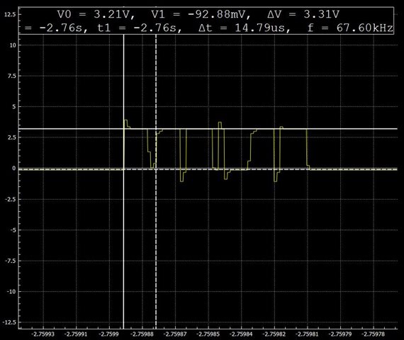
This is what the readback mode waveform looks like:

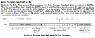
I delay 1ms then send 0 pulses to read the EEPROM contents but the output oscillation never stops. I can tell because the clock drives a RISC-V core which I have running an LED binary counter application and it continues normally. If I disable the CDCE421A it halts the application. I'd expect the same behavior when in readback mode.

I've exhausted all options I can think of to get this working including reading the few posts about it here multiple times. Is there anything else I can try?

  • Christopher,

    Do you have the waveform for the input that you are providing to the device for beginning the readback process?

    Thanks,

    Kadeem

  • Hi Kadeem,

    This is the readback waveform I'm using. I'm sending all zeros. I tired with ones but it made no difference.

    High pulse of 1 / 70000 * 0.2 = 2.85us

    Low pulse of 1 / 70000 * 0.8 = 11.4us

  • Christopher,

    Are you sending the preliminary pulse to trigger EEPROM readback after sending the first six pulses?

    Is only a single programmable clock required? The LMK61E2 may prove easier to use in a microcontroller-based implementation (I2C over proprietary interface with stricter timing requirements).

    Thanks,

    Kadeem

  • Yes, I'm sending all the required pulses.

    LMK61E2 would have been a better choice. Unfortunately, this chip is already on the boards we're using.

  • Christopher,

    Just to be clear: 

    1. You are seeing changes on the output when you use this programming method, correct? I am assuming that this is the case based on your previous statement: "which works well based on the result on seeing on the output."
    2. If this is not the case, for the readback access pulses, are you meeting the timing requirement of 0.2t for the low time?

    Thanks,

    Kadeem

  • Kadeem,

    I am not seeing changes on the output of the CDCE421A. The output I'm taking about is the output of the microcontroller to the SDATA pin on the CDCE421A. This is where I've captured the wave forms I've shown above. I have the timing set right at 0.2t where t = 1/70000. It's possible it's too close to the threshold between the longer '1' pulses. I can try delaying it some.

  • Christopher,

    Thank you for the clarification. I have placed an order for an evaluation module so that I can take a capture of the "ideal" waveform and provide it as a guide for how the communication should look. This should arrive late next week.

    I will provide an update when I have the evaluation module with captures.

    Thanks,

    Kadeem

  • Kadeem,

    I'm glad to hear that. I considered doing the same and appreciate you taking the initiative on it. I did try adding a delay between bits while keeping the high pulse widths the same but it did not help.

    I've triple checked the CDCE421A board layout and continuity from the SDATA pin of the CDCE421A  to the microcontroller pin but haven't found any issues.

    I'm looking forward to seeing your captures.

    Chris

  • Christopher,

    I have been informed by the inventory team that there are no evaluation modules for this device in stock.

    The delay time between rising CE and the first pulses is at least 3T? How long is the rise time of the pulse, is it near 2ns or substantially faster?

    I understand that the board is designed and fabricated, but we highly recommend moving to the LMK61E2 for replacing the CDCE421A.

    Thanks,

    Kadeem