Other Parts Discussed in Thread: LMK04832
Hi team,
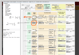
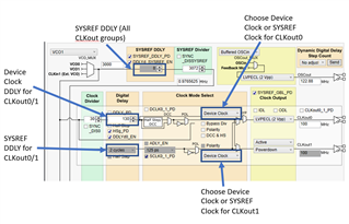
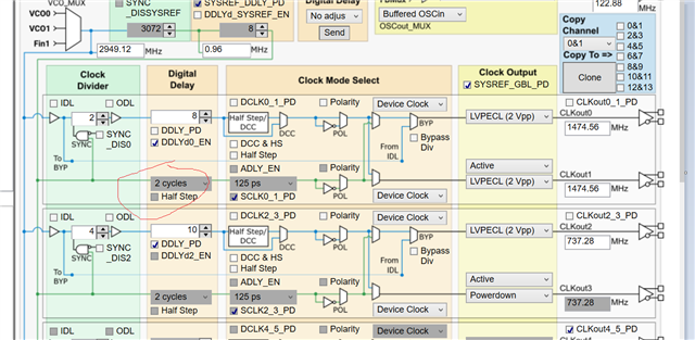
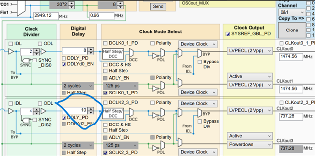
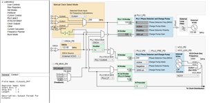
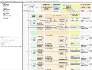
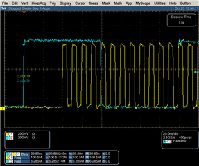
I want have two clocks with LMK04832EVM , one is 6.25M ,another is 16×6.25M 。and the two clocks have 90° phase difference.can you show me how to configure it. thanks.
Hi team,
I want have two clocks with LMK04832EVM , one is 6.25M ,another is 16×6.25M 。and the two clocks have 90° phase difference.can you show me how to configure it. thanks.


 :
: