This thread has been locked.

If you have a related question, please click the "Ask a related question" button in the top right corner. The newly created question will be automatically linked to this question.

LMX2594PSEVM: Programming each of the two synthesizers separately

Part Number: LMX2594PSEVM
Other Parts Discussed in Thread: LMX2594, , TIDA-01410

I have the LMX2594PSEVM, which contains two LMX2594 synthesizers and therefore two RFout SMA connectors. However, When ever I program one synthesizer (Turning off the switches of the other synthesizer), the other one provides the same RFout frequency (As if they always have to be programmed to provide the same outputs)!

I need to generate two different signals; one at 4GHz and the other at 4.4 GHz. Do I need to modify the connections of the board to achieve this goal or is it possible with the provided connection of the LMX2594PSEVM to get two different output frequencies?

Thank you 

Mohammad Alafari

  • Mahammad,

    Not sure what the LMX2594PSEVM is, but we have a reference design TIDA-01410 ( https://www.ti.com/tool/TIDA-01410 )  that has two synthesizers that can be individually programmed.  The SCK and SDI lines can be shared, but the CSB has to be individually used.  This design has switches for control. 

    Regards,
    Dean

  • Hello Dean,

    LMX2594PSEVM ( https://www.ti.com/tool/LMX2594PSEVM ) is almost the same as TIDA-01410, it has the same two synthesizers and (Total 8) switches for control. However, when I turn off the switches for the first synthesizer (CSB, SCK, SDI, Readback) and keep the 4 switches for the second synthesizer ON then program it, I get the same output frequency from both synthesizers as if I programmed them both together (Not only one of them).

    Do you switch off all the 4 switches or only the CSB, to program one synthesizer only? 

    Note: I use TICS Pro software to program my LMX2594PSEVM.

    Thank you 

  • Hi Mohammad,

    I will turn all four switches to the OFF position when I am not program it, so far I have never see your problem. The DIP switch has pretty good isolation when it is OFF. 

    Maybe try do some modifications to the board.

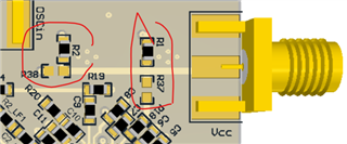
    1. move resistor R2 to R38 and move R1 to R37. This will bypass the LDOs, so Vcc should be 3.3V. 

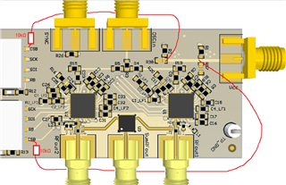
    2. pull both CSB pins to Vcc via 10kΩ resistor.

    This will ensure the non-program device will not be programmed by crosstalk from the switch.