This thread has been locked.
If you have a related question, please click the "Ask a related question" button in the top right corner. The newly created question will be automatically linked to this question.
Hello,
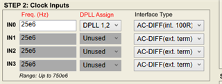
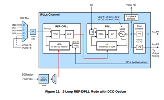
I have a design working with the LMK05028. I am attempting to use it in the 2 loop; REF, APLL mode.
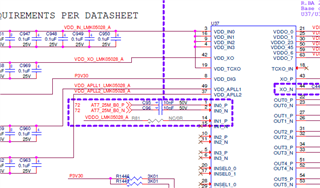
I have a LVDS input on IN0 at 25MHz and an XO at 48MHz. I'm using both PLL1 and 2 to output 100MHz and 312.5MHz respectively.
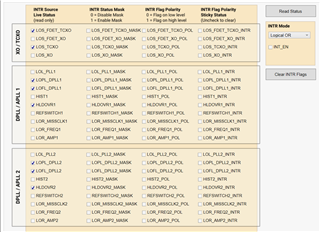
When I enable the frequency detect threshold, the PLL gets stuck in holdover mode regardless of the valid PPM settings.
If I disable the frequency detect during the validation state, the PLL reports it is frequency locked but it never shows as phase locked.
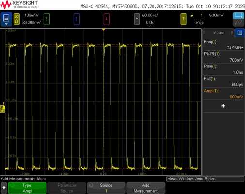
When I probe the input and the output I can see there is no correlation between the phases.
Attached is the TCS file. Please let me know if I am missing something in the setup or if there is a way to debug the settings.
Thanks,
Ben Hirt
Hi Jennifer,
Thanks for your reply. I attempted to use the tcs file you sent but the PLL remains in holdover according to the status registers. It appears the reference input is still not passing the validation stage. I attempted a few different settings for the frequency detect threshold but it doesn't change anything. Would you have any recommendations on how to debug this further?
Thanks,
Ben Hirt
Hi Ben,
Can you share a schematic snippet of the input? I would like to understand the terminations you use for the LVDS. Do you set the register settings for 100 ohm internal termination for INx pins?
Please also provide a waveform scope shot when probing at the INx pins.
Regards,
Jennifer
Hi Jennifer,
Here is the snippet of the schematic. It is AC coupled LVDS on the input.
I set the internal termination to AC-DIFF (int. 100R) and attached the input clock scope captures.
Differential input to the device.
When I probe the single ended lines on the input side to the PLL I can see the DC bias point set to about 1.6V.
Thanks,
Ben Hirt
Ben,
The team is currently out for the Thanksgiving holiday. Please expect a response by Monday (PST) for any further queries.
Thanks,
Kadeem
Ben,
I tested with a similar setup as you: 25 MHz LVDS signal (VOD = 400 mV) --> AC-coupling caps --> IN0 of LMK05028 using int. 100 ohm termination.
With your original configuration, I cannot phase lock.
With the Oct 30 2023 config, I can lock.
This implies it is not a core DPLL configuration issue, but a question of the reference validation, as you had assumed.
The next step is to identify the failing validation setting. Please disable each validation setting one by one and check the status each time you disable. For example, disable frequency detect threshold, then check Status. Does the reference validate? Does the DPLL lock? If so, then this is the problematic threshold. If not, continue disabling the next such as Missing Clock...and so on.
Hey Jennifer,
Thanks for looking into this. After getting the eval board and playing around with a few things, we were able to get the PLL to lock. After reviewing the path, it was found that the input clock to the PLL was actually derived from a spread spectrum source which was causing the validation stage to fail and ultimately preventing the PLL from locking properly. After changing the input we're now getting it to lock in system. Thanks again for your time and support.