This thread has been locked.

If you have a related question, please click the "Ask a related question" button in the top right corner. The newly created question will be automatically linked to this question.

LMK05028EVM: Default .tcs file

Part Number: LMK05028EVM
Other Parts Discussed in Thread: LMK05028, LMK5C33216, LMK5B33216, LMK05318B, LMK5C33216A, LMK5C33216EVM

Hello 

I bought a LMK05028 EVM. I have several questions 

1) Do you know where I can find the initial .tcs file that is load into the EEPROM?  

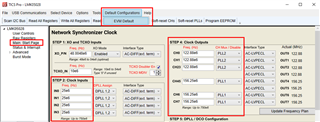
I would like to modify it and test with our generator that can give maximum 5 MHz instead of 25MHz ( EVM Quick Start, snau223).

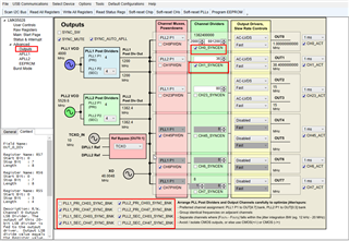
2) With the LMK05028 EVM, I would connect a PPS to IN0 (1Hz) and I would like to have the following ouputs:

- A PPS (out 0) in LVDS, 

- 38,4 MHz synchronised to the input PPS and phase aligned with PPS out0,

Do you have .tcs file for testing?

Thank you

best, regards

Patrice

  • Hi Patrice,

    In the tool bar of TICS Pro on the top of the page, there is a button for Default Configurations. This is the config used for EEPROM. You can download the latest TICS Pro software at: https://www.ti.com/tool/TICSPRO-SW#downloads

    The "Main: Start Page" is where you can modify your inputs and also choose PLLx to generate the outputs needed.

    Section 9.3.10 in the datasheet describes the settings to synchronize between outputs: https://www.ti.com/lit/ds/symlink/lmk05028.pdf?ts=1699391522316&ref_url=https%253A%252F%252Fwww.google.com%252F

    The "Outputs" page contains these bits to enable for phase synchronization.

    I do not have a .tcs file. Please give it a try on creating the config and let me know if you have other questions.

    -Riley

  • Hello Riley,

    Thank you for your answers and your help. I test first at 30 MHz, I created .tcs file (Test_PPS_30MHz).

    I have tested it, with a GPS module (UBLOX M8T) connected to GPS ANTENNA for the PPS_IN.

    • IN0_N is connected to GND;
    • IN0_P to PPS_IN (yellow)
    • OUT0_P to PPS_OUT (green)
    • OUT1_P to 38, MHz(orange)


    I trig with the PPS IN, there are a drift with the output. It seems not lock.

    D12/D13 are ON (DPLL1/2 not locked) and D8/D9 are ON (DPLL1/2 holdover active).

    My question is

    • Can we connect a PPS 3V3 instead of 1V8 (IN0_P)? It seems to be 2V the limit.
    • The PPS_OUT (OUT0_P) can we configured the length (length of activation)
    • According to the tcs file, do you know why it does not lock (outputs drift), leds are ON?


    I put in the EEPROM too the Test_PPS_30MHz.tcs, no lock.


    Please find attached the TICS pro configuration file for reference.

  • Patrice,

    The team is currently out for the Thanksgiving holiday. Please expect a response by Monday (PST) for any further queries.

    Thanks,

    Kadeem

  • Hi Patrice,

    After further discussion with the team, we do not recommend using LMK05028 for 1-PPS inputs as there are issues with the DPLL locking. The LMK5B33216 (for ethernet clocks) or LMK5C33216 (for wireless applications) are newer technology that can handle 1-PPS and should be used instead.

    Regards,

    Jennifer

  • Hello Jennifer,

    Thank you for your answers.

    For the LMK5B33216 (for ethernet clocks) or LMK5C33216, It seems ZDM is not possible with 1-PPS. Do you confim it?

    1) Do you have a component that can have 1-PPS input and output with a deterministic phase (phase between input and output known)?

    Other points.

    2) Can we connect a PPS 3V3 instead of 1V8 (IN0_P)?

    3) The PPS_OUT (OUT0_P) can we configured the length?

    Thank you,

    Best regards,

    Patrice


  • Note : For ZDM, I can generate an input PPS with 50 % cycling 

  • Hi Patrice,

    • We have recently done more testing with 1-PPS and ZDM and we were able to get a configuration that phase locks. However, there are contingencies.
    • Does your application require the DPLL to lock to more than 1-PPS or just one?
      • There could be problems if there is more than 1-PPS input. If one input is lost, when the DPLL tries to switch over to the next input, it could take hours to relock due to the wide LBW and slow lock times, causing the DPLL to rail off. That's why we do not recommend 1-PPS + ZDM for more than one 1-PPS input.

    Regards,

    Jennifer

  • Hello Jennifer,

    Thank you for your answers. It seems to be OK.

    My configuration will be :

    One Input : PPS will be connected to one input IN0_P (on pulse per second, CMOS 1V8 or 3V3 TBD). 

    - IN0_N, IN1_P, IN1_N will not be connected. 

    Two ouputs : 1 PPS out (LVDS) and one 38,4 MHz (CMOS)

    What is the difference between LMK5B33216 and LMK5C33216?

    I only see the difference on RMS jitter. There are pin compatible.

    Do you think the output Phase Noise will better for one of those components?

    Thank you,

    Regards,

    Patrice

  • Hi Patrice,

    The LMK5B/5C are an improvement over the LMK05318B and will have better performance.

    The difference between 5B and 5C is the frequency of the Voltage-Controlled Bulk Acoustic Wave Oscillator (VCBO) on APLL3. With the BAW technology, we are able to achieve excellent jitter performance for APLL3 outputs.

    The VCBO of the 5B is centered around 2500 MHz to get frequencies such as 100 MHz, 156.25 MHz, 312.5 MHz..

    The VCBO of the 5C is centered around 2457.6 MHz to get frequencies such as 122.88 MHz, 245.76 MHz, 491.52 MHz.

    We recommend choosing 5B or 5C depending on your application: 5B is for wired communications whereas 5C is for wireless communications. Since you want to generate 38.4 MHz, I recommend picking LMK5C33216.

    Each device has two additional APLLs containing LC-VCOs for additional frequency domains; they also provide great jitter performance but are not as high performing as the VCBO.

    Regards,

    Jennifer

  • Hello Jennifer,

    We will command the LMK5C33216 Evaluation.

    Thank you,

    Regards,

    Patrice

  • Hi Patrice,

    • Can you please elaborate on the end equipment/project use case as well as the volume?
    • Also, what is your timeline for this project? We are about to release an improved version of the LMK5C33216 (called LMK5C33216A). It is not yet on ti.com but should be this month. I just want to make sure you get the most recent device/EVM ordered.
    • Alternatively, you can also get the LMK5C33216EVM and replace it with an LMK5C33216A part.

    Regards,

    Jennifer

  • Hello Jennifer,

    We have ordered LMK5C33216EVM, yesterday (ti.com).

    After testing, I would integrate the clock synchronizer in a board. I should finish the board schematic at the end of january.

    I think we will ask to replace the LMK5C33216EVM with an LMK5C33216A part.

    Thank you for your help,

    Regards,

    Patrice

  • Hi Patrice,

    Understood, thanks for sharing the timeline. Please make separate thread for LMK5C33216, should there be further questions.

    Regards,

    Jennifer