This thread has been locked.

If you have a related question, please click the "Ask a related question" button in the top right corner. The newly created question will be automatically linked to this question.

LMX2594EVM: Pullup method investigation

Part Number: LMX2594EVM
Other Parts Discussed in Thread: LMX2594,

Hi,

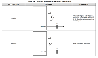
We are using LMX2594 for new project and when I checked the datasheet of LMX2594EVM, I am curious about the 18nH inductor between power supply and 50Ohm pullup resistors. What exactly the purpose of this 18nH inductor here ? Any explanations ?

In case where I need 1nH inductor pullup for 12GHz for example, should I keep this inductor in series with my 1nH pullup inductior anyway?

Thanks in advances,

Best regards,

XL

  • Hi XL, 
    Refer to page 60 of device datasheet. 

    If you're output frequency is 12 GHz, I am pretty confident you will require a very small inductor in 0201. 
    You will have to check cap parameters and check the SFR (self-resonnant-freq) of the inductor to ensure it's close to your target output frequency. 

    Regards, 

    Vicente 

  • Hi Vincente,

    I appreciate your response but this donesn't answer my question... I will try a small package inductor whose SRF is enough high for that for sure.

    But I still don't know why there is a low-Q18nH inductor (L1, L2) in series with 50Ohm pullup resistor on the EVM... Is it used as a power supply filter in combination of 0.01uF bypass capacitor (C6, C11) for noise? Or just a RF choke? Should I keep this inductor for inductor pullup method with 1nH for example?

    Thanks.

    BR,

    XL 

  • Hi XL,

    L1 is not the pull-up in the schematic, the pull-up are the 50Ω resistors. L1 is served as a RF choke.