A related question is a question created from another question. When the related question is created, it will be automatically linked to the original question.
If you have a related question, please click the "Ask a related question" button in the top right corner. The newly created question will be automatically linked to this question.
LMK04832: How to enable LMK04832 pulse sysref mode
I noticed that the title asks about pulsed SYSREF mode, but the question asked about one shot SYSREF mode - these are two different things, and I want to make sure we answer your question in either case:
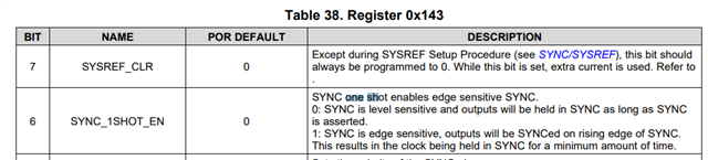
One Shot SYNC is a function that inserts a one-shot pulse circuit between the output of the SYSREF mux and the SYSREF distribution path. Because the SYNC and SYSREF distribution paths are shared, this is more useful for SYNC than it is for SYSREF. One shot SYNC converts the SYSREF distribution path from a level-sensitive mode, where a logic HIGH/LOW signal produces a logic HIGH/LOW output on SYSREF channels, to an edge-sensitive mode, where a rising edge from any signal on the SYSREF_MUX will trigger a logic HIGH pulse for just the number of clock distribution path cycles required to reset all the dividers. The difference is, in the edge-sensitive mode, holding the SYNC signal in logic HIGH will indefinitely reset dividers; in the edge-sensitive mode, holding the SYNC signal in logic HIGH will not change how long the dividers are in reset after a SYNC signal rising edge. Andrea described in her answer how to enable one shot SYNC mode.
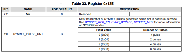
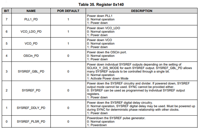
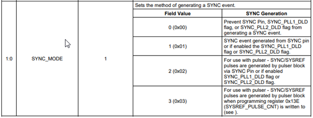
SYSREF Pulser Mode is a way to produce only a specific number of SYSREF pulses for every SYSREF request. The SYSREF_PD (0x140[2]) and SYSREF_PLSR_PD (0x140[0]) fields should be cleared to 0 to power up both the SYSREF divider and the pulser circuit. The SYSREF_PULSE_CNT (0x13E[2:0]) field can be programmed with the appropriate number of SYSREF pulses. The SYSREF_MUX field (0x139[1:0]) should be set to 2 for pulser mode. Triggering the SYSREF pulser depends on the setting of the SYNC_MODE (0x143[1:0]) field:
If SYNC_MODE is set to 2, the SYNC pin signal (or optionally the SYNC_PLL1_DLD or SYNC_PLL2_DLD signals) triggers the pulser circuit. Each rising edge at the SYNC pin will trigger the number of pulses programmed by SYSREF_PULSE_CNT.
If SYNC_MODE is set to 3, writing register 0x13E triggers the pulser, and produces the number of pulses programmed by SYSREF_PULSE_CNT during that register write. For example, if SYNC_MODE==3, 0x13E == 0x03, and you write 0x01 to 0x13E, the pulser will be triggered two times.
For the SYSREF pulser mode, the pulses are just a gated copy of the SYSREF divider. So the pulse duration and phase alignment relative to the device clocks will be the same as for continuous SYSREF. For example, if the SYSREF divider is programmed to produce 1MHz output, triggering the pulser will produce pulses with a period of 1MHz and a pulse width of 1 / (2 * 1 MHz). Since the pulser is just gating the SYSREF divider, the SYSREF divider needs to be synchronized to the clocks for proper alignment. Datasheet sections 8.3.4.1 and 8.3.5 offer guidance on how to ensure the SYSREF divider is aligned to the device clocks as desired.