This thread has been locked.

If you have a related question, please click the "Ask a related question" button in the top right corner. The newly created question will be automatically linked to this question.

LMK61E2: output impedance question

Part Number: LMK61E2

Hi

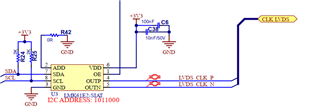
i am using the LVDS Clock lmk61e2-siat
The LVDS clk (circuit1) signals is send to circuit 2 (the circuit 2 has the 100 ohm resistor) via a flex Cable.

before to connect the flex and second circuit, i made an impedance check, to be sure nothing is short.

the resistor read between clk-P and Gnd is 45K ohm
the resistor read between clk-N and gnd is 50 ohm  (i expect, it is not correct,and/or maybe the clk is not working correctly)

Do you have a idea what is the impedance From output CLK-P and CLK-N to GNd  should be acceptable?

regards

  • Hi Stephane, 

    Are you measuring the output impedance of the LMK61E2 on it's own, or is it soldered on to a board? If it's on a board already, can you share a schematic?

    Also, is the part turned on or off while you're taking these measurements? 

    Regards, 

    Connor 

  • Hi Connor

    there is no power at all.
    It is only an impedance test with multimeter.

    CLK-LVDS go to connector


    regards
    Stephane

  • Hi Stephane, 

    Thanks for providing the schematic. I did a quick check on a unit in the lab when it was powered off and I was measuring 250K Ohm to GND for both OUTP and OUTN. Can you try just powering up the 1st board and measuring the output of the LMK61E2? Seeing the waveform for OUTP and OUTN would be a good way to debug any possible issues. A 50 Ohm to GND connection on the output shouldn't damage the part, but ideally you can set a current limit on the power supply just in case. 

    Regards, 

    Connor