This thread has been locked.

If you have a related question, please click the "Ask a related question" button in the top right corner. The newly created question will be automatically linked to this question.

CDCE62002: CDCE62002 has temperature Characteristics for lock time?

Part Number: CDCE62002


Hi,

We are using CDCE62002 for Jitter cleaning.

The device seems to have temperature Characteristics for lock time.

Because,

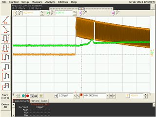
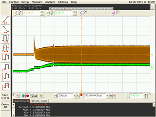
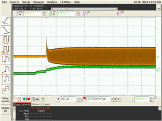
 1. We input signal when the package is about 100℃, then CDCE62002 does not lock.

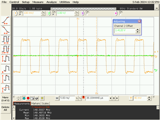
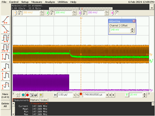
 2.  As the package temperature drops, CDCE62002 becomes lock state. The package is about 75.

Sometime the duration between 1 and 2 is a few minutes. The Reproducibility is high.

Do you have any information about this symptoms?

And  we would like to know θJC. Only θJA is described in datasheet.

Thank you

  • Hello,

    The CDCE62002 is only rated for a package temperature up to 85 C:

    Above 85 C, the device may not function as expected. 

    This could potentially be a loop filter stability issue as well, see this thread: https://e2e.ti.com/support/clock-timing-group/clock-and-timing/f/clock-timing-forum/139983/cdce62002-temperature-problems?tisearch=e2e-sitesearch&keymatch=cdce62002%252520temperature#


    I will do some digging on the RθJC value. Expect an update by Friday on whether or not this is information that we have available.
    Thanks,
    Kadeem

  • Hello,

    RθJC_top is 31 °C/W , and RθJC_bottom is 1.69 °C/W.

    Thanks,

    Kadeem

  • LCOK_EXT-LFN.pptx

    Hello,

    We measured Lock signal and EXT-LFN.

    Sometime EXT-LFN becomes higher voltage, then it takes long time to Lock.

    Refer to attached file.

    Is that normal operation?. We can't fine out the mechanism.

    We use Ext. loop filter. C1=1uF、C2=47uF、R2=12Ω.  LFRCSEL=b'0100.

    Best Regards,

    LCOK_EXT-LFN.pptx

  • Hello,

    I do not believe that this is typical behavior. Is this at the 100C that you mentioned previously?
    Is this behavior still observed when using the internal loop filter in place of the external loop filter?

    When using the loop filter tool in the CDCE62002 GUI, are these the loop filter component values that are recommended by the tool for your configuration?
    Thanks,

    Kadeem

  • Is this at the 100C that you mentioned previously?

      No. It is about 60℃。The longer the PD(register2 bit[7]=0), the more likely it tends to occur.

     Refer to attached file, I added "Lock detection flow". Please confirm it.

    Is this behavior still observed when using the internal loop filter in place of the external loop filter?

     I will Check it.

    We would like to make the BW narrow, we decided loop filter setting by GUI.

    And、are there individual differences?  For example lot, production date etc.1856.LCOK_EXT-LFN.pptx

    Best Regards,

  • Hello,

    Is the CALSELECT bit (R2[13]) set to a '0' or a '1'? When this bit is a '0', the PLL will be recalibrated when the /PD bit is toggled. If set to a '1', the PLLRESET bit controls recalibration. If the CALSELECT bit is changed, does the issue still occur?

    We have not had reports of this behavior being seen in large quantities in a specific lot. Is this behavior seen on only a single part, or on multiple devices? How many parts experience this issue?
    Thanks,

    Kadeem

  • We tried internal filter, but nothing appears on EXT-LFN. I think the EXT-LFN is disconnect when use internal filter.

    And the lock time is still long.

    Is the CALSELECT bit (R2[13]) set to a '0' or a '1'? When this bit is a '0', the PLL will be recalibrated when the /PD bit is toggled.

     Yes, It is set to '0'.

    Is this behavior seen on only a single part, or on multiple devices? How many parts experience this issue?

    It is not on only single part, I'm not sure but it is about 1/10.

    Please let me know,

    •  What is the difference between CALSELECT =1 and CALSELECT =0?
    •  How is the device status when PD=0?
    •  If we expand Lock window, what is negative side effect? (0x00[14:13]=00 now)

    Have a happy new year.

    Best Regards,

  • Hello,

    Table 14 summarizes the behavior of the CALSELECT pin below:

    The /PD = 0 behavior is described here:

    The /PD bit, unlike the /PD pin, does not reload the register contents from the EEPROM.

    The lock detect window is described below:

    These settings for adjusting the lock detect window are useful when the frequency of the input clock is variable.

    This thread gives an example of such a case: https://e2e.ti.com/support/clock-timing-group/clock-and-timing/f/clock-timing-forum/764816/cdce62002-input-clock-tolerance/2827882?tisearch=e2e-sitesearch&keymatch=cdce62002%252520window#2827882

    Can you please provide the full schematic? It is unusual that the unlock time would be on the order of seconds. I would expect the EXT_LFN pin to rise more quickly as well.

    Thanks,
    Kadeem

  • Schematics.pptx

    Hi,

    I send you schematic of CDCE62002.

    Please refer to attached file.

    Best Regards,

  • Hello,


    We will take a look at this on the evaluation module, and let you know if we can replicate this issue. Please expect a response by Monday (PST).

    Can you please provide the register configuration for the device?
    Thanks,

    Kadeem

  • Hello,

    I provide you the register configuration.

    Please refer to attached file.

    /* Reg0 */
    Reg0[7:0] = 05
    Reg0[15:8] = 02 
    Reg0[23:16]= 0b 
    Reg0[31:24] =01 
    
    /* Reg1 */
    Reg1[7:0] = 06
    Reg1[15:8]= 2e
    Reg1[23:16]= 38 
    Reg1[31:24]= 08 
    
    /* Reg2 */
    Reg2[7:0] = eb 
    Reg2[15:8]= 03
    Reg2[23:16]= 10 
    Reg2[31:24]= 06 
    

    Best Regards,

    /* Reg0 */
    Reg0[7:0] = 05
    Reg0[15:8] = 02 
    Reg0[23:16]= 0b 
    Reg0[31:24] =01 
    
    /* Reg1 */
    Reg1[7:0] = 06
    Reg1[15:8]= 2e
    Reg1[23:16]= 38 
    Reg1[31:24]= 08 
    
    /* Reg2 */
    Reg2[7:0] = eb 
    Reg2[15:8]= 03
    Reg2[23:16]= 10 
    Reg2[31:24]= 06 
    

  • Hello,

    I had a mistake about loop filter setting.

    I use external filter and Reg1[25:22] = b'0100.

    Best Regards,

  • Hello,

    With the setting corrected, is the long lock time no longer occurring?
    Thanks,
    Kadeem

  • Hello,

    With the setting corrected, is the long lock time no longer occurring?

    No. The lock time is long.

    I'm sorry I confused you. Reg1[25:22] = b'0100 is our current setting and long lock time.

    The text file which I send you was mistake.

    Best Regards,

  • Hello,

    Currently Kadeem is out of office and wont be back until next week. He will be able to continue supporting you around that time.

    Best,

    Andrea

  • Hello,

    We will take a look at this on the evaluation module, and let you know if we can replicate this issue. Please expect a response by Monday (PST).

    How is the progress?

    Were there any problems?

    Best Regards,

  • Hello,

    Apologies for the delay. We have tried to use your register configuration on an EVM and noticed an issue in the data. 

    Figure 35 on page 35 of the datasheet shows the command structure. I wanted to highlight Reg0[3:0] which should all be 0 to correlate with the register number. In your data you had Reg0[7:0] = 05 which does not correlate with the command structure. Is this a typo? This same issue occurs for registers 1 and 2, as well.

    Additionally, it may be helpful to include the data formatted similarly to Figure 35 for comparison. I attached a txt file for an example.

    Best,

    Cris

    Original:
    
    /* Reg0 */
    Reg0[7:0] = 05
    Reg0[15:8] = 02 
    Reg0[23:16]= 0b 
    Reg0[31:24] =01 
    
    /* Reg1 */
    Reg1[7:0] = 06
    Reg1[15:8]= 2e
    Reg1[23:16]= 38 
    Reg1[31:24]= 08 
    
    /* Reg2 */
    Reg2[7:0] = eb 
    Reg2[15:8]= 03
    Reg2[23:16]= 10 
    Reg2[31:24]= 06 
    
    
    Figure 35 Format:
    Reg 0: 00000001 0000101100 0000100000 0101
    Reg 1: 0000001000 0011100000 1011100000 0110
    Reg 2: 0000000110 0001000000 0000111110 1011

  • Hello,

    The txt file is log of our internal tool.

    For example Reg0[7:0] means following.

    Best Regards,

  • Hello,

    What is the PRIREF frequency being inputted to the device? It is not clear from your schematic and is not available in the register dump.

    Best,

    Cris

  • Hello,

    In this case, the input is 297MHz and output is 148.5MHz.

    Best Regards,

  • Hello,

    Thank you for your response. We are working to see if we can replicate this issue on our EVM. Expect a response by Monday.

    Best,

    Cris

  • Hello,

    We have tested your configuration at room temperature and found no issues. Tomorrow we will test at 60C and see if we can replicate the issue.

    Best,

    Cris

  • Hello,

    As additional information, the longer the PD=0 time(more than 15 minutes), the more likely it is to occur.

    For example, we use the setting "INBUFF=OFF and PD=0" when there is no input.

    It occurs when a signal is input after several minutes.

    Best Regards,

  • Hello,

    We have set this up for testing today and will have results tomorrow.

    Thanks,

    Kadeem

  • Hello,

    We have been able to replicate your issue on the bench. 

    Is the CALSELECT bit (R2[13]) set to a '0' or a '1'? When this bit is a '0', the PLL will be recalibrated when the /PD bit is toggled. If set to a '1', the PLLRESET bit controls recalibration. If the CALSELECT bit is changed, does the issue still occur?

    When we toggled /PD with CALSELECT being 0, the device was able to relock. Does this produce the same result for you? How about when CALSELECT is 1 and PLLRESET is toggled?

    Best,

    Cris

  • When we toggled /PD with CALSELECT being 0, the device was able to relock. Does this produce the same result for you? How about when CALSELECT is 1 and PLLRESET is toggled?

     I'll try these procedures, give me a moment, please.

     How is the EXT_LFN voltage when you replicate the issue?

    Can you see the waveform?

    Best Regards,

  • I noticed that we toggle PD bit in device control loop after signal input.

    So  I think recalibration seems not to be effort.

    Now we are going to try not to set PD=0 during no signal for countermeasure.

    Could you guess the mechanism of the issue ? I need to explain to my team.

    Best Regards,

  • Hello,

    The designers that developed this part are no longer present - we may not be able to dig into the chip design for details.
    We are not able to probe the loop filter pin on the EVM while the board is in the chamber at this temperature.

    I see improved performance (no unlock) at higher temperature - from previous threads there is discussion of loop filter instability across temperature, does using this filter option yield no unlock on your end?


    Thanks,

    Kadeem

  • Hello,

    The designers that developed this part are no longer present - we may not be able to dig into the chip design for details.

    I am very sorry to hear that.

    We are not able to probe the loop filter pin on the EVM while the board is in the chamber at this temperature.

    Can you measure it somehow?

    I thought it was more likely to occur in high temperature. But it wasn't.

    It occurs normally at room temperature, depends on PD duration.

    I will try new loop filter setting.

    Best Regards,

  • Hello,

    This is measured at room temperature. Initial startup:

    The clock waveform settles with an output frequency at about 148.5MHz:

    Thanks,

    Kadeem

  • Hello,

    Thank you for  wave forms.

    I would like to see wave form of EXT_LFN while unlock state.

    How long Does the unlock state continue on your EVM?

    Best Regards,

  • Hello,

    My apologies for not clarifying - the EXT_LFP pin is shown in green in the above images, with the output clock in orange.

    The device is locking at startup, with the clock settling at the correct level in <0.1ms.
    I can try to force an unlock condition by removing the input clock and send a capture of the pin with the device unlocked.

    Thanks,

    Kadeem

  • Hello,

    Below is the capture of the output clock and the EXT_LFN pin when the device is locking on startup:

    This is the result on the EXT_LFN pin when the 297MHz clock is not applied:

    And this is the result when the device is powered on with the external clock, and then the clock is turned off:

    The device is only unlocked when not provided with the input clock - as soon as the input is applied again the device locks.

    What I do observe is this: If the input clock is ready before the device is powered on, then the CDCE62002 locks with no issue, and will re-lock if the input clock is removed and then provided later. If the input clock is provided after power-on, then the CDCE62002 does not lock.

    Thanks,

    Kadeem

  • Hello,

    If the input clock is ready before the device is powered on, then the CDCE62002 locks with no issue, and will re-lock if the input clock is removed and then provided later. If the input clock is provided after power-on, then the CDCE62002 does not lock.

    Does the "power-on" mean PD=1?

    If your CDCE62002 does not lock, how long unlock state continue?

    A few dozen seconds? or a few minutes?

    Best Regards,

  • Hello,

    When the device is unlocked in my case, it is only unlocked because I am disconnecting the input clock (there is no holdover functionality in this part).

    The device remains unlocked until the reference clock is provided again - after providing the clock is it is a few ms for the device to lock again. Power-on in this case is referring to full power cycle, or PD toggle.

    Thanks,

    Kadeem

  • Hello,

    I was mistaken.

    Cris Kobierowski reproduce our issue.

    So I would like to know unlock time and EXT_LFN wave form of his reproducing.

    Best Regards,

  • Hello,

    Understood. Cris will be returning to the office tomorrow - I will discuss their procedure with them to understand where we are not aligned.
    Thanks,
    Kadeem

  • Hello,

    When trying to recreate the issue again today in the lab, we discovered that the source in my setup had an issue with the duty cycle. This is what caused the CDCE62002 to not be able to lock. Upon correcting the issue with the source, I had the same results as Kadeem. The CDCE62002 locked fine and did not have any issues, even at 60C in the temp chamber with PD=0 for an extended period of time. I apologize for the confusion.

    Best,

    Cris