This thread has been locked.

If you have a related question, please click the "Ask a related question" button in the top right corner. The newly created question will be automatically linked to this question.

CDCE62002 EVM Software settings for PLL lock

Other Parts Discussed in Thread: CDCE62002

Hello:

I am having issues setting register values in the CDCE62002 EVM Software.  Specifically, I cannot setup the device to ensure PLL lock.  I have a 10MHz input signal and wish to decrease the phase jitter on a 20MHz output signal.

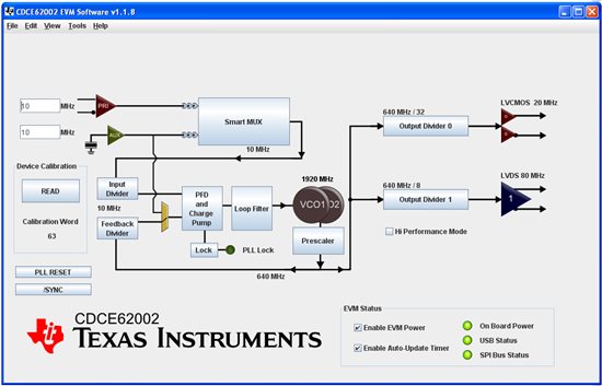
Attached is a screen shot with the current settings.

What are the correct settings to enable PLL lock?  What are the correct SPI settings?  Here are my current Reg 0 -- 2 settings:

Register 0: 647800e0; Register 1: bd002001; Register2: 20003812


Thanks!

Kerri

  • Hi Kerry,

    I verified that the EVM can handle your intended frequency plan in the lab and it did. However, a few things are important.

    Input Mux: I suspect your EVM has an XTAL installed, and you apply 10MHz on PRI input, correct? You need to set your input mux to PRI input only. Right now your configuration shows "auto-mux", which causes the mux to go wrong because the input signals need to be within 10% frequency of each other. If you select PRI input only, the device ignores the AUX input, and gets rid of this problem. So if you only use the primary input, you should set Reg0.3=0 instead of 1.

    Input configuration of input buffer: Based on your input buffer bit selection, you are driving the device with a PECL source, correct? (any AC coupled differential signal should actually work with this setting). Make sure that you drive both the P and the N input with a differential signal. Also, please check on your EVM that the P and N input have an AC coupling cap installed (mine had a zero-ohm on P-input, so I had to use an AC coupling cap on my input cable to make it work).

    GUI usage: Here is what I recommend you do to be sure the GUI is working good. (1) Start GUI (2) disable "enable auto-update timer" checkbox. (3) Provide reference clock of 10MHz. (4) load INI-file. (5) calibrate PLL by: (5.1)Tools/SPIDebug (5.2) select Reg-2 (5.3) set Reg 2.13=0 and then toggle Reg2.7=1-->0-->1 (reference Tab-20 in data sheet. Be sure to ignore the GUI names for Reg 2.7 and Reg 2.13. they are wrong. The data sheet has authority. We will release an improved GUI very soon.)

    Here is a set of working registers I've used:

    Reg0: 64780060
    Reg1: 3d002001
    Reg2: 61003db2 (read only)

    You can download this file here and import it into your GUI from the File-menu: http://e2e.ti.com/cfs-file.ashx/__key/CommunityServer-Discussions-Components-Files/48/0702.CDCE62002_5F00_working_5F00_file.ini

    Charge Pump current & loop filter: Your settings indiciate that you are using a charge pump current of 3.75mA, an external loop filter, and an internal 3rd pole of R3C3~830kHz (tau=5MHz). Make sure that your external loop filter on the EVM is enabled. The dip switches SW9 and SW10 enable the loop filter. They are located on the bottom side of the EVM. Make sure only one loop filter is enabled, and not several. You can use Filter 1 (highest BW) or Filter 4 (lowest BW) to check the different noise performance you get. If you are concerned that maybe you don't have the external loop filter enabled properly, you can also pick an internal loop filter instead. Click on the GUI block labeled "Loop Filter" to see all your options. Also, for jitter cleaning, you may want to use a loop filter setting with a lower 3rd pole.  (See EVM application note page 8 and page 10: http://www.ti.com/litv/pdf/scau034

    Furthermore, make sure the external loop filter you plan on using is stable. You can find the latest loop filter tool at: http://e2e.ti.com/cfs-file.ashx/__key/CommunityServer-Components-UserFiles/00-00-01-01-11-Attached+Files/3312.LoopFilterTool_5F00_Setup_5F00_rename_5F00_exe.txt 

    Select active loop filter. Mimick the settings below or simply load the following ini-file: http://e2e.ti.com/cfs-file.ashx/__key/CommunityServer-Discussions-Components-Files/48/3426.Filter1_5F00_simu_5F00_3p75mA.tps


    Best regards. Fritz

  • PS: On additional comment: If you write the settings into EEPROM, you can power-cycle the device and it should automatically lock to your 10MHz reference clock, assume REFCLK is valid at power up. I think you EEPROM settings were locked - so be sure to unlock the EEPROM with the GUI before you write to it.

  • Thanks for the help, Fritz.  That worked perfectly for the 10MHz in to 20MHz out...Is there any way we can go from a 5MHz in to a 10MHz out?  If that isn't possible, can we go from a 10MHz in to a 5MHz out? 


    --Kerri